
Method and device for adjusting panorama imaging as well as panorama imaging device

一种全景成像、调整方法的技术,应用在光学、仪器、闭路电视系统等方向,能够解决成像器件像素利用率低、无用信息多等问题,达到提高像素利用率、提高成像质量的效果

Active Publication Date: 2010-12-29
PUWELL TECH
View PDF5 Cites 9 Cited by
  • Summary
  • Abstract
  • Description
  • Claims
  • Application Information

AI Technical Summary

Problems solved by technology

[0003] The inventor found through the research on the prior art that when the existing panoramic imaging equipment is applied to the occasion where the peripheral vision requirement of the same pitch angle is less than 360 degrees, there is a lot of useless information and the pixel utilization rate of the imaging device is low

Method used


Image

  • Method and device for adjusting panorama imaging as well as panorama imaging device
  • Method and device for adjusting panorama imaging as well as panorama imaging device
  • Method and device for adjusting panorama imaging as well as panorama imaging device

Examples


Embodiment Construction

[0041] The embodiment of the present invention discloses a panoramic imaging adjustment method and device as well as a panoramic imaging device. In order to make the purpose, technical solution and advantages of the present invention clearer, the present invention will be described in further detail below with reference to the accompanying drawings and examples.

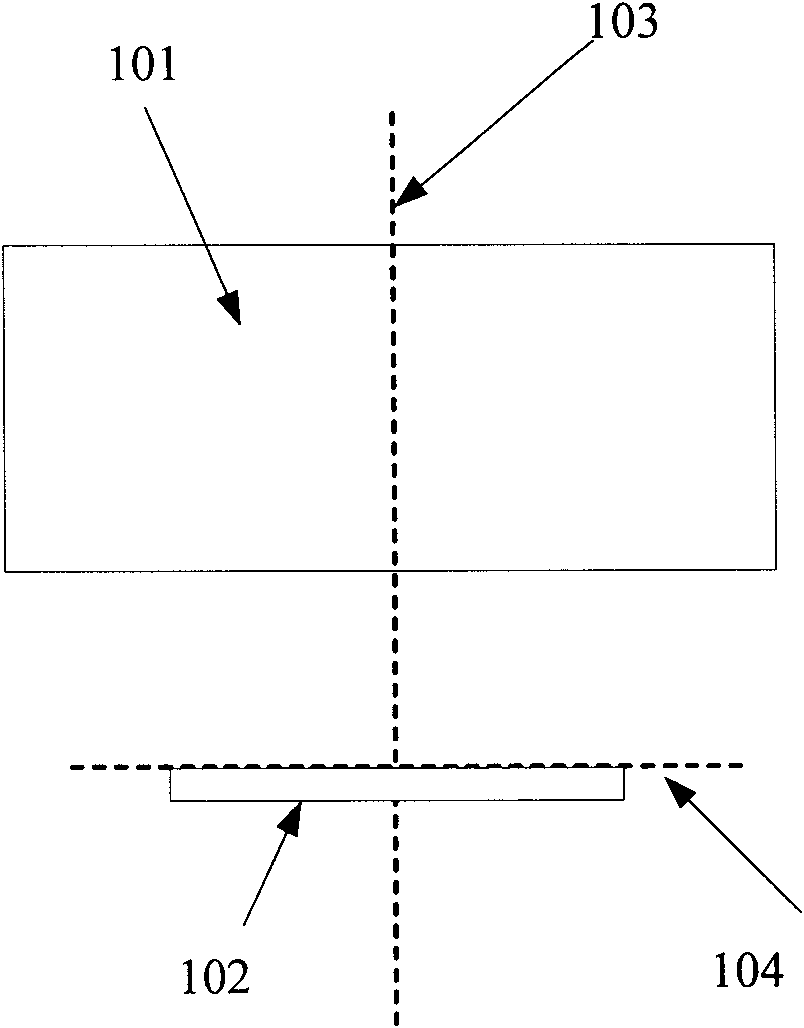
[0042] The existing panoramic imaging principle structure is as follows: figure 1 As shown, the imaging device 102 is located on the focal plane 104 of the panoramic lens 101, and the optical axis 103 of the panoramic lens 101 passes through the geometric center of the imaging device.

[0043] The panoramic lens described in the embodiment of the present invention refers to the optical system of the "Catadioptric Omni-directional Imaging System (Catadioptric Omni-directional Imaging System)" in the professional field. The panoramic lens mentioned below has the same meaning and is no longer repeat.

[0044] The exist...


PUM


Abstract

The embodiment of the invention discloses a method and a device for adjusting panorama imaging as well as a panorama imaging device. The method comprises the following steps: determining the panoramic angle and the pitch angle of a current region to be detected; determining the side length of a rectangular imaging device in the panorama imaging device; adjusting a round panorama image of a panoramic lens formed on a focal plane according to the side length of the rectangular imaging device as well as the panoramic angle and pitch angle of the current region to be detected so as to enable the diameter of the round panorama image of the panoramic lens formed on the focal plane is larger than the short side length of the rectangular imaging device. By utilizing the method provided by the embodiment of the invention, the pixel utilization ratio of the imaging device is effectively improved in the occasion that the panoramic requirement of the pitch angle is less than 360 degrees; and the imaging quality is improved.

Description

technical field [0001] The invention relates to the technical field of video monitoring, in particular to a panoramic imaging adjustment method and device and a panoramic imaging device. Background technique [0002] The current panoramic monitoring equipment is mainly composed of panoramic lens and CCD / CMOS imaging components. The analog video signal output is connected to the panoramic video server, and the panoramic video server transmits the unfolded image to the monitoring room or directly to the monitor for monitoring. show. Panoramic camera is a new kind of panoramic monitoring equipment, without using multiple cameras, a single panoramic camera can realize 360-degree blind spot monitoring of a large space. figure 1 It is a schematic structural diagram of the principle structure for realizing 360-degree panoramic imaging in the prior art. As shown in the figure, the imager 102 is located on the focal plane 104 of the panoramic imaging lens, and the optical axis 103 ...

Claims


Application Information

Patent Timeline
Patent Type & Authority Applications(China)
IPC IPC(8): G03B37/00H04N7/18
CPCH04N7/18G03B37/06G02B13/06
Inventor 李捷李必勇
Owner PUWELL TECH
Learn More