On-vehicle heater and its manufacturing method

A manufacturing method and heater technology, which are applied in the directions of heating element material, heating element shape, ohmic resistance heating, etc., can solve problems such as leakage

Active Publication Date: 2011-01-05
田口 浩四郎
View PDF1 Cites 17 Cited by
  • Summary
  • Abstract
  • Description
  • Claims
  • Application Information

AI Technical Summary

Problems solved by technology

[0005] In the heater disclosed in Patent Document 1, the electrode member, the heat sink, and the PTC element are electrically connected,

Method used


Image

  • On-vehicle heater and its manufacturing method
  • On-vehicle heater and its manufacturing method
  • On-vehicle heater and its manufacturing method

Examples


Embodiment Construction

[0020] Hereinafter, embodiments of the present invention will be described with reference to the drawings.

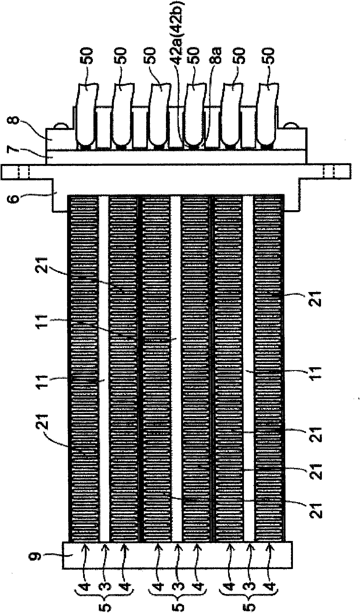
[0021] figure 1 It is a plan view of the vehicle heater according to the embodiment of the present invention.

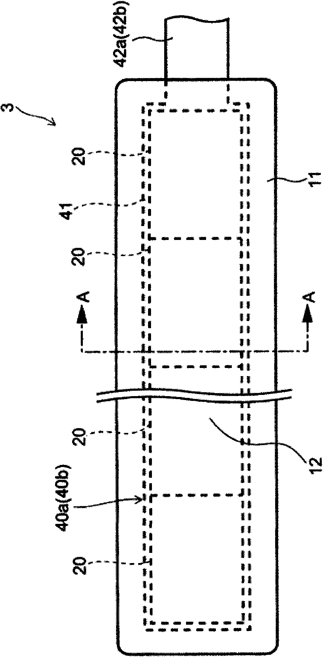
[0022] The vehicle heater of this embodiment has a structure in which a plurality of heating element units 3 containing heating elements inside a cylindrical body 11 and a plurality of heating element units 4 having cooling fins 21 are stacked. For example, one heater unit 5 is constituted by sandwiching one heat generating unit 3 between two heat radiating unit 4 .

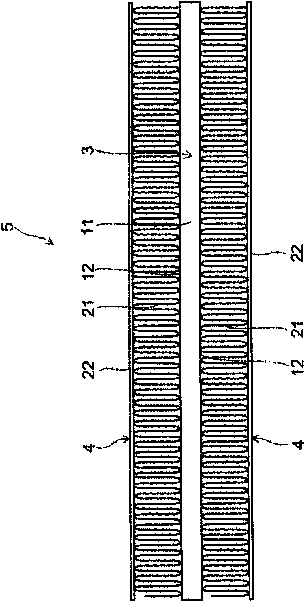
[0023] The vehicle heater of the present embodiment has, for example, a structure in which three heater units 5 are stacked. figure 2 One heater unit 5 is shown enlarged and extracted.

[0024] The heat radiator unit 4 has a heat sink 21 and a metal plate 22 . The heat sink 21 is configured by bending a plate made of, for example, aluminum in a zigzag shape, and is provided between the metal...


PUM


Abstract

An on-vehicle heater comprises a heating body unit including a heating element, an electrode member stacked on and in contact with the heating element, an insulation sheet for enveloping the heating element and electrode member, and a tubular body which stores the heating element and electrode member enveloped by the insulation sheet; a radiator unit stacked on the heating body unit; and a cap attached to an end part of the heating body unit. The electrode member includes a terminal portion which is led out to the outside the tubular body from an opening formed in an end part of the tubular body and then is bent and penetrates the cap to be led out from the cap.

Description

technical field [0001] The present invention relates to an on-vehicle heater mounted on an automobile, and more particularly to an on-vehicle heater using a PTC (Positive Temperature Coefficient) element as a heat source. Background technique [0002] Generally, as the main heat source for heating the interior of an automobile, a warm water heater that uses the waste heat of the engine cooling water to heat the air is used. Electric heaters. In addition, it is conceivable that the installation of electric heaters will be promoted as electric vehicles become popular in the future. [0003] A PTC element is often used as a heating element of an electric heater (for example, Patent Document 1). In the PTC heater disclosed in Patent Document 1, heat sinks are arranged above and below the PTC element, and a heater unit in which electrode members are provided in contact with the heat sink has a two-layer laminated structure. [0004] Patent Document 1: Japanese Patent Applicati...

Claims


Application Information

Patent Timeline
IPC IPC(8): H05B3/20B60H1/03B60H1/22
CPCB60H2001/2278H05B3/50H05B2203/023Y10T29/49002F24H3/0441B60H1/2225H05B1/0236H05B3/03H05B3/04H05B3/14H05B2203/017H05B2203/02
Inventor 田口浩四郎
Owner 田口 浩四郎
Why Eureka
Try Eureka