High-accelerated speed linear electromagnetic propelling system

A linear electromagnetic and propulsion system technology, applied in the direction of propulsion systems, electromechanical devices, electric vehicles, etc., can solve the problems of low power factor of linear induction motors, achieve the effect of increasing acceleration and payload, reducing capacity and cost, and improving efficiency

Active Publication Date: 2012-06-27
HARBIN INST OF TECH
View PDF0 Cites 0 Cited by
  • Summary
  • Abstract
  • Description
  • Claims
  • Application Information

AI Technical Summary

Problems solved by technology

[0003] The purpose of the present invention is to solve the problem of low power factor of the linear induction motor in the high-acceleration linear electromagnetic propulsion system, and to provide a high-acceleration linear electromagnetic propulsion system

Method used


Image

  • High-accelerated speed linear electromagnetic propelling system
  • High-accelerated speed linear electromagnetic propelling system
  • High-accelerated speed linear electromagnetic propelling system

Examples


specific Embodiment approach 1

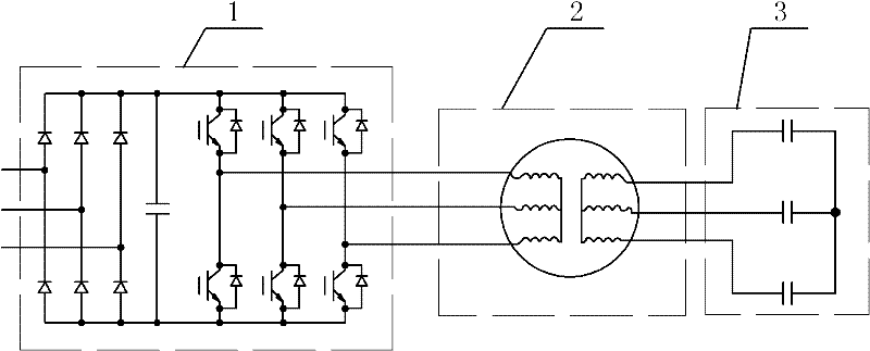
[0019] Specific implementation mode one: the following combination figure 1 , figure 2 and image 3 Describe this embodiment, this embodiment is made up of power converter 1, linear motor 2 and excitation capacitor 3,

[0020] Each capacitor in the exciting capacitor 3 is connected in a star shape or a polygon;

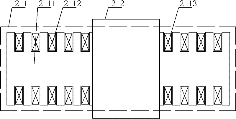
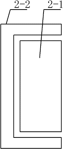
[0021] The linear motor 2 includes an armature 2-1 and a secondary 2-2, the secondary 2-2 is in the shape of a gate, the two vertical sides of the secondary 2-2 gate are conductor plates, and the inner side of the conductor plate is a low-resistivity metal material, the outer side of the conductor plate is a high magnetic permeability metal material; the secondary 2-2 straddles the armature 2-1, and the inner side of the secondary 2-2 is separated from the upper surface and both sides of the armature 2-1 by an air gap relatively;

[0022] The armature 2-1 is composed of the main iron core 2-11, the main winding 2-12 and the auxiliary winding 2-13. -13 is embedde...

specific Embodiment approach 2

[0025] Specific implementation mode two: the following combination Figure 4 and Figure 5 Describe this embodiment. The difference between this embodiment and Embodiment 1 is that it also includes two auxiliary iron cores 2-14, one auxiliary iron core 2-14 is provided on both sides of the air gap side of the armature 2-1, and the secondary The outer sides of each vertical edge of the 2-2 door shape are respectively opposite to an auxiliary iron core 2-14 separated by an air gap. Other components and connections are the same as those in Embodiment 1.

[0026] In this embodiment, the two auxiliary cores 2-14 are not slotted.

specific Embodiment approach 3

[0027] Embodiment 3: The difference between this embodiment and Embodiment 1 or 2 is that each of the main winding 2-12 and the auxiliary winding 2-13 is a set of annular windings or there is a set of each in the slots on each side of the main core 2-11. A main winding 2-12 and a set of auxiliary windings 2-13. Other compositions and connections are the same as those in the first or second embodiment.


PUM


Abstract

The invention relates to a high-accelerated speed linear electromagnetic propelling system, belonging to the technical field of motors and solving the problem of low power factor of a linear induction motor in the high-accelerated speed linear electromagnetic propelling system. Respective capacitors in an exciting capacitor are connected into star shape or polygon; the secondary stage is a door shape; two vertical sides of the secondary door shape are conductive plates; the secondary stage is crossed on an armature; the inner side of the secondary stage is opposite to an air gap on the upper surface of the armature and the surfaces at both sides; a tooth groove structure is arranged at the air gap side on both sides of a primary iron core; a primary winding and an auxiliary winding are inlayed in the grooves on both sides of the primary iron core; a leading-out terminal of the primary winding is connected with the output end of a power inverter; and the leading-out terminal of the auxiliary winding is connected with the leading-out terminal of the exciting capacitor. On the basis of the scheme, the armature is additionally provided with two auxiliary iron cores, the auxiliary winding is inlaid on the tooth groove structure of the auxiliary iron core and the outer side of each vertical side of the secondary door shape is opposite to the auxiliary iron core air gap. The invention is suitable for a linear electromagnetic propelling system.

Description

technical field [0001] The invention relates to a high-acceleration linear electromagnetic propulsion system, which belongs to the technical field of motors. Background technique [0002] Typical applications of high-acceleration linear electromagnetic propulsion systems include trains driven by linear motors, such as subway trains and high-speed maglev trains, and electromagnetic ejection of aircraft carriers. When the train leaves or enters the station, it generally needs to use a high-acceleration linear electromagnetic propulsion system to control the train to accelerate or decelerate at a constant high acceleration; and when a carrier-based aircraft uses an electromagnetic catapult to take off from the ship, it also needs to use a high-acceleration linear electromagnetic propulsion system. The system applies a constant high thrust, ie high acceleration, to the aircraft. Linear induction motors are widely used in linear propulsion systems due to their simple structure, ...

Claims


Application Information

Patent Timeline
IPC IPC(8): H02K41/02B60L13/10
Inventor 寇宝泉张鲁张赫
Owner HARBIN INST OF TECH
Why Eureka
Try Eureka