Permanent-magnetic speed regulator

A permanent magnet speed governor, permanent magnet technology, applied in the direction of asynchronous induction clutch/brake, etc., can solve the problems of large space, small torque, inability to apply, etc., to achieve high efficiency, large torque, and reduce vibration.

Inactive Publication Date: 2011-01-19
QINGDAO SIPURUI ELECTROMECHANICAL TECH
View PDF3 Cites 21 Cited by
  • Summary
  • Abstract
  • Description
  • Claims
  • Application Information

AI Technical Summary

Problems solved by technology

[0003] The disadvantage of this utility model is that the torque transmitted between the magnetic rotor and the conductor rotor is small, and the space required for the same power transmission is larger, so that it cannot be applied in many occasions.

Method used


Image

  • Permanent-magnetic speed regulator
  • Permanent-magnetic speed regulator
  • Permanent-magnetic speed regulator

Examples


Embodiment Construction

[0024] The permanent magnet governor of the present invention will be further described below in conjunction with specific embodiments.

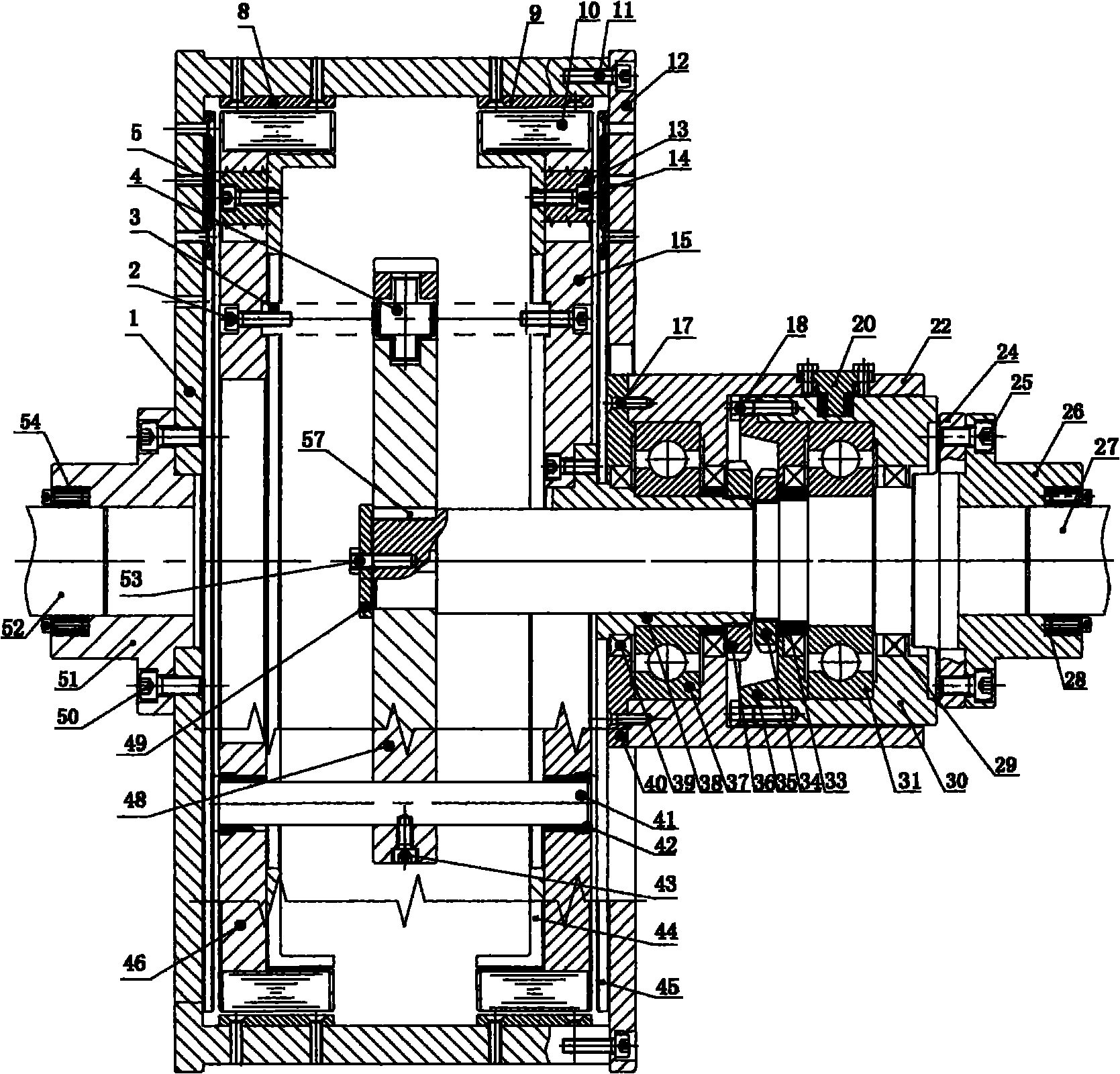
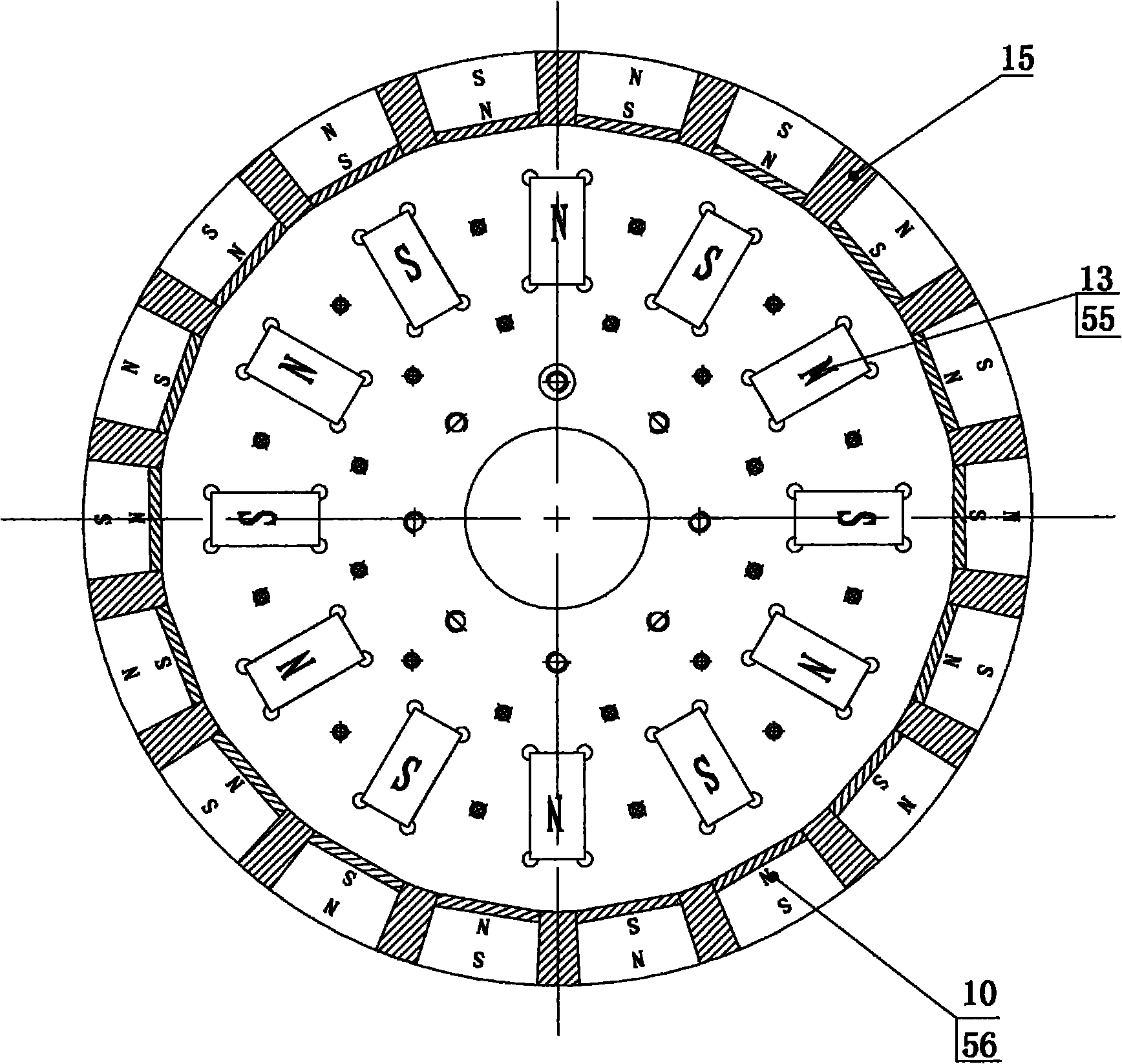
[0025] Working principle: The magnets on the permanent disk and the side cylinder are arranged adjacent to the N and S poles. The magnetic field lines pass through the corresponding conductor disk and the conductor cylinder. When the two move relative to each other, the conductor disk and the conductor cylinder are cut separately The lines of magnetic force generate eddy currents in the conductor disk and the conductor cylinder, and the eddy currents then generate a repulsive magnetic field to prevent relative movement between the two, thereby realizing torque transmission between the two. The greater the intensity of the magnetic field passing between the two, the greater the torque transmitted; the faster the relative movement, the greater the torque transmitted; the greater the speed difference, the greater the repulsive force between the two...


PUM


Abstract

The invention discloses a permanent-magnetic speed regulator, which comprises a first shaft, a second shaft, a cage rotor and permanent-magnetic turntables. A permanent-magnetic rotor comprises two disk permanent-magnetic turntables and a central turntable, wherein the central turntable is connected with the second shaft, and the permanent-magnetic turntables are connected with the central turntable through a pin shaft and a gear rack device; and the gear rack device comprises racks vertically arranged on the permanent-magnetic turntables and a gear arranged on the central turntable, the racks are engaged with the gear, and the gear rack device enables the two permanent-magnetic turntables to do reverse equidistance motion along the shaft. The double-cylindrical turntable permanent-magnetic speed regulator has large coupling face by replacing cylindrical and planar double coupling for single-side coupling, and realizes non-contact transmission of power with large transmission torque; the permanent-magnetic turntables can move along the axial direction to change the distance from a conductor plate and the effective part engaged with a conductor cylinder so as to change the torque transferred between the permanent-magnetic turntables; and the permanent-magnetic speed regulator can realize repeatable, adjustable and controllable output torque and rotational speed and fulfill the purposes of energy-saving speed regulation, and has balanced axial force.

Description

Technical field [0001] The invention relates to a drive speed regulating device, in particular to a permanent magnet speed regulator adopting the principle of permanent magnet eddy current induction. Background technique [0002] The utility model patent 98802726.7 filed by Magnafus Corporation on February 20, 1998, discloses an adjustable magnetic coupling, which has: two conductor rotors mounted on the first rotating shaft and mounted on the second rotating shaft Each of the above includes two permanent magnet rotors with a corresponding set of permanent magnets; the two permanent magnet rotors are located between the two conductor rotors, and an equal air gap is maintained between each permanent magnet rotor and the corresponding conductor rotor. The air gap can be increased or decreased at the same time under the action of the push-pull mechanism, and the change of the air gap corresponds to the change of the output torque to adjust the output speed of the load. [0003] The s...

Claims


Application Information

Patent Timeline
Patent Type & Authority Applications(China)
IPC IPC(8): H02K49/04
Inventor 王荣松李昌村赵强谭文胜谢玉斌陈玉忠
Owner QINGDAO SIPURUI ELECTROMECHANICAL TECH
Why Eureka
Try Eureka