Aircraft propeller vector engine
A vector engine and aviation propeller technology, applied in the direction of machines/engines, non-variable engines, aircraft parts, etc., can solve the problems of poor vertical take-off and landing maneuverability of fixed-wing propeller aircraft, and achieve mature technical implementation conditions and sealing The effect of good performance and structural safety
- Summary
- Abstract
- Description
- Claims
- Application Information
AI Technical Summary
Problems solved by technology
Method used
Image

Examples
Embodiment 1
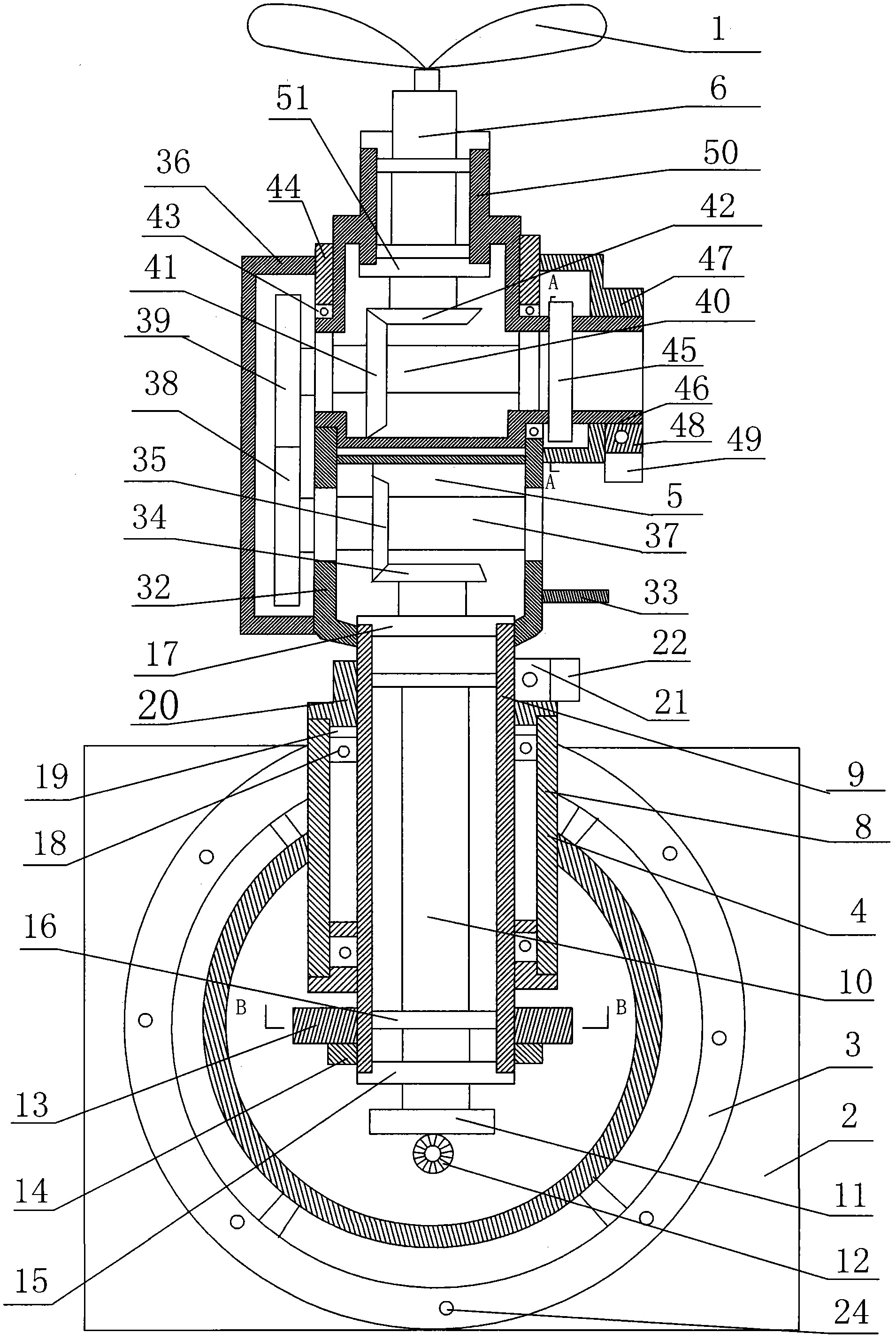
[0021] Aviation propeller vector engine, its composition includes: propeller 1, engine 2, described engine 2 is connected with connection seat 3, and described connection seat 3 is connected with universal power transmission device 4, and described universal power transmission device 4 is connected with universal power transmission device The universal arm 5 is connected to the propeller connecting shaft 6, and the propeller connecting shaft 6 is connected to the propeller.
Embodiment 2
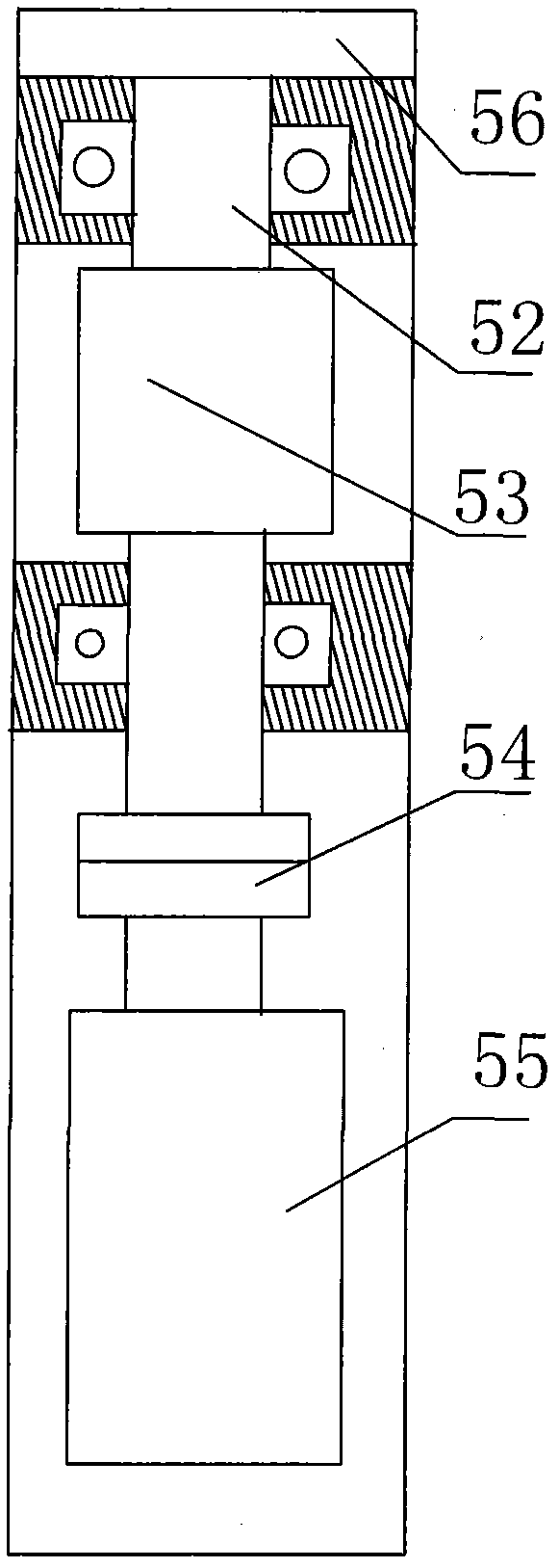
[0023] In the aviation propeller vector engine described in Embodiment 1, the universal power transmission 4 includes a steering cylinder base 8, and the steering cylinder base 8 is connected to a steering cylinder 9, and a steering shaft 10 is housed in the steering cylinder 9 , the steering shaft 10 is connected to the universal power transmission gear 11, the universal power transmission gear 11 is connected to the transmission gear 12, and one end sleeve of the steering cylinder 9 is connected to the steering wheel 13 and the tightening nut 14, so The lower end of the steering cylinder 9 is equipped with a steering cylinder gland 15, a sealing ring 16 is installed between the steering cylinder 9 and the steering shaft 10, and one end of the steering cylinder seat 8 is connected to the steering cylinder seat gland 17. , the upper and lower ends of the steering cylinder seat 8 and the steering cylinder 9 are respectively equipped with a steering cylinder bearing 18 and a stee...
Embodiment 3
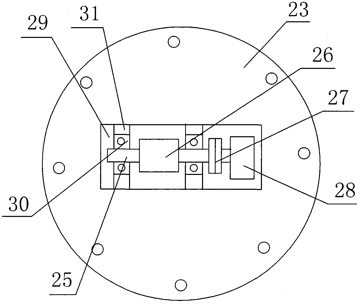
[0026] In the aviation propeller vector engine described in Embodiment 1 or 2, the universal arm 5 includes a sector gear box 32, and the sector gear box 32 is connected to the steering cylinder 9, and the sector gear set is housed in the sector gear box 32 One side of the sector gear box 32 is connected to the bracket 33, the sector gear set includes a lower horizontal gear 34 and a lower vertical gear 35, the lower horizontal gear 34 is connected to the steering shaft 10, and the lower vertical gear Gear 34 is connected with lower transmission shaft 37, and described lower transmission shaft 37 is connected with lower gear 38, and described lower gear 38 is connected with upper gear 39, and described upper gear 39 is connected with upper transmission shaft 40, and described upper transmission shaft 40 Connect the upper vertical gear 41, the upper vertical gear 41 is connected to the upper horizontal gear 42, and the upper horizontal gear 42 is connected to the propeller conne...
PUM
 Abstract
Description
Claims
Application Information
 - R&D Engineer
- R&D Manager
- IP Professional
- Industry Leading Data Capabilities
- Powerful AI technology
- Patent DNA Extraction
Browse by: Latest US Patents, China's latest patents, Technical Efficacy Thesaurus, Application Domain, Technology Topic.
© 2024 PatSnap. All rights reserved.Legal|Privacy policy|Modern Slavery Act Transparency Statement|Sitemap