Leveling system of laser leveling instrument and debugging method thereof
A debugging method and technology of a leveling instrument, which are applied in the field of leveling systems, can solve problems such as weakening of elasticity, deviation, and change of the position of 18B of the blister tube, so as to avoid positioning deviation, reduce debugging time, and simplify the debugging method.
- Summary
- Abstract
- Description
- Claims
- Application Information
AI Technical Summary
Problems solved by technology
Method used
Image
Examples
Embodiment 1
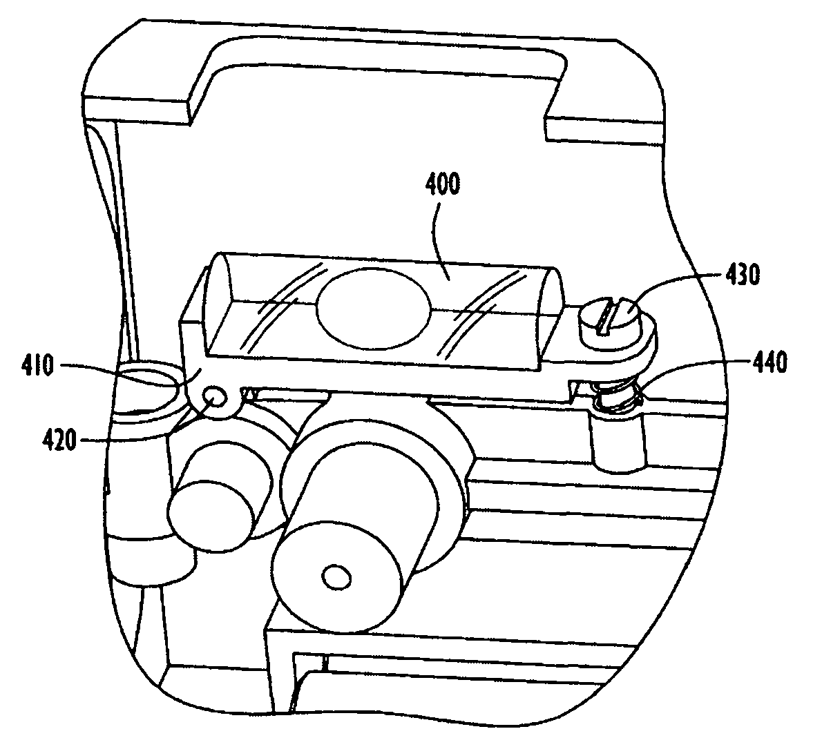
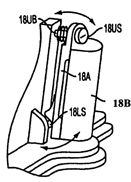
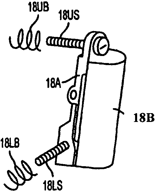
[0046] Embodiment 1 of the leveling system of the laser leveling instrument of the present invention includes a horizontal installation and debugging part, and the horizontal installation and debugging part will be described in detail below. Such as Figure 4 , Figure 5 , Image 6 as shown, Figure 4 It is a schematic diagram of the three-dimensional structure of Embodiment 1 of the leveling system 10 of the laser leveling instrument of the present invention; Figure 5 for Figure 4 The view of the leveling system 10 of the laser leveling instrument shown in the X direction; Image 6 for Figure 4 An enlarged exploded view of part A in Fig. The leveling system 10 of the laser leveling instrument of the present invention includes a rotating component 20 , a main body 12 , a first bubble tube 14B and a second bubble tube 13B. The rotating part 20 has a laser beam exit hole 30 along the axis of the rotating part 20 . The light exit hole 30 is used to emit a positioning l...
Embodiment 2
[0075] The second embodiment of the leveling system of the laser leveling instrument of the present invention includes not only the horizontal installation and debugging part, but also the vertical installation and debugging part.
[0076] The detailed description of the vertical installation and debugging part of the leveling system of the laser leveling instrument in this embodiment is as follows:
[0077] Such as Figure 8 , Figure 9 , Figure 10 , Figure 11 as shown, Figure 8 It is a schematic diagram of the three-dimensional structure of Embodiment 2 of the leveling system of the laser leveling instrument of the present invention; Figure 9 for Figure 8 The view along the X direction of the leveling system of the laser leveler shown in ; Figure 10 for Figure 8 The enlarged exploded view of part C in the figure; Figure 11 for Figure 9 Enlarged view of part D in Fig. The vertical installation and commissioning part of the leveling system 10 of the laser le...
Embodiment 3
[0099] Embodiment 3 of the leveling system of the laser leveling instrument of the present invention can also be realized by the following structure and debugging method:
[0100] Such as Figure 13 , Figure 14 , Figure 15 with Figure 16 As shown, the difference between this kind of vertical installation and adjustment part and the above-mentioned vertical installation and adjustment part is only that the connection method between the adjustment seat 15T' and the main body 12 is different. The upper end of the back plate 150 of the adjustment seat 15T' is rotatably connected to the fixed plate 12P' through a cylindrical pin 21, and the axis of the cylindrical pin 21 is perpendicular to the axis of the bottom wall adjusting screw 18, that is, parallel to the Y-axis direction. The specific structure is: the cylindrical pin 21 is arranged on the upper wall 152T' of the joint seat 15T'. The upper end of the fixed plate 12P' is provided with two corresponding lugs 121, and t...
PUM
 Abstract
Description
Claims
Application Information
 - R&D
- Intellectual Property
- Life Sciences
- Materials
- Tech Scout
- Unparalleled Data Quality
- Higher Quality Content
- 60% Fewer Hallucinations
Browse by: Latest US Patents, China's latest patents, Technical Efficacy Thesaurus, Application Domain, Technology Topic, Popular Technical Reports.
© 2025 PatSnap. All rights reserved.Legal|Privacy policy|Modern Slavery Act Transparency Statement|Sitemap|About US| Contact US: help@patsnap.com


