Manual-release electromagnetic brake of cam crankshaft

An electromagnetic brake and manual release technology, which is applied in the direction of brake parts, brake actuators, slack adjusters, etc., can solve the problems of slow speed and achieve the effects of high efficiency, convenient and clean operation, and fast braking speed

Active Publication Date: 2012-10-10
JIANGXI HUAWU BRAKE
View PDF0 Cites 0 Cited by
  • Summary
  • Abstract
  • Description
  • Claims
  • Application Information

AI Technical Summary

Problems solved by technology

The current manual release devices for electromagnetic brakes generally use screw release, which is slow; there is also a lever-pull release form, which has no air gap adjustment device, so it is urgent to design an efficient and reliable release mechanism for electromagnetic brakes.

Method used


Image

  • Manual-release electromagnetic brake of cam crankshaft
  • Manual-release electromagnetic brake of cam crankshaft
  • Manual-release electromagnetic brake of cam crankshaft

Examples


Embodiment Construction

[0013] The following embodiments will further illustrate the present invention in conjunction with the accompanying drawings:

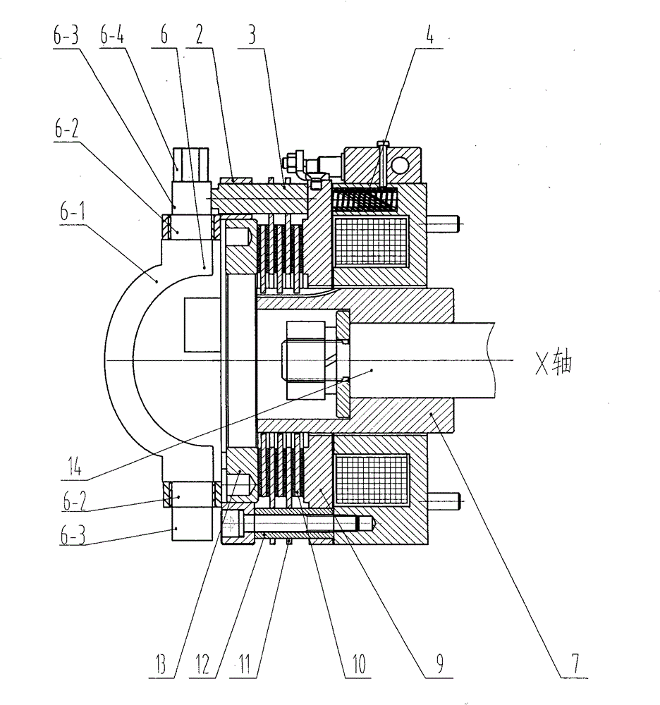
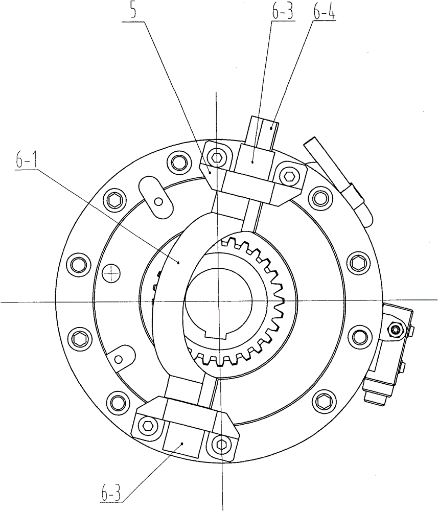
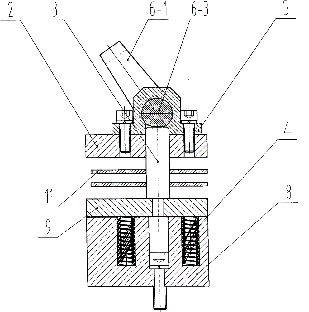
[0014] Referring to the accompanying drawings, the present invention is a normally closed electromagnetic brake, including a braking mechanism and a manual release mechanism. The brake mechanism consists of a power controller 1, an outer flange 2, a compression spring 4, an outer spline hub 7, an electromagnet 8, an armature plate 9, a moving friction plate 10, a fixed friction plate 11, a spacer 12 and an adjusting top ring 13 . The manual release mechanism is composed of a release top post 3, a release base 5 and a cam crankshaft 6. The outer flange 2 has two through holes, both of which are equipped with release top posts 3 , the release base 5 is installed on the outer plane of the outer flange 2 circles, and the cam crankshaft 6 is installed on the two release bases 5 . The cam crankshaft 6 comprises a semicircular crankshaft 6-1 positioned at ...


PUM


Abstract

The invention discloses a manual-release electromagnetic brake of a cam crankshaft. The manual-release electromagnetic brake comprises a braking mechanism and a manual-release mechanism, wherein the manual-release mechanism consists of release support pillars, release pedestals and a cam crankshaft; an outer flange is provided with two through holes in which the release support pillars are placed; the release pedestals are mounted on the outer plane of the outer flange ring; the cam crankshaft is mounted on the two release pedestals; the cam crankshaft comprises a semicircular crankshaft positioned at the middle part, a shaft neck and a cam which are positioned at both ends of the crankshaft; an outer hexagonal driving head is arranged at the outer end of one of the cams; and one end of each release support pillar is tightly attached to one face of the corresponding cam, and the other end of the release support pillar is tightly attached to an armature disk. The manual-release electromagnetic brake of a cam crankshaft is rational in design, and convenient to mount and demount; and under an electricity-lost state, the cam crankshaft has high brake removal speed, and is safe and reliable. Due to the inbuilt electromagnet, an adjusting top ring quickly, conveniently and accurately adjusts air gaps. Therefore, compared with the prior art, the manual-release electromagnetic brake is convenient to operate and high in power efficiency, and is more applicable to machine engineering.

Description

technical field [0001] The invention relates to a brake, in particular to a power-off normally closed electromagnetic brake with built-in electromagnet release and cam crankshaft manual release structure. Background technique [0002] The manual release of the electromagnetic brake is used for transmission mechanism maintenance, power failure, or electromagnet failure when the equipment needs to be rotated and other working conditions. The current manual release devices for electromagnetic brakes generally adopt screw release, which is slow; there is also a lever-pull release form, which has no air gap adjustment device, so it is urgent to design an efficient and reliable release mechanism for electromagnetic brakes. Contents of the invention [0003] The purpose of the present invention is to overcome the shortcomings of the existing electromagnetic brake products, and provide a reasonable design, convenient installation and disassembly, and reliable manual release when p...

Claims


Application Information

Patent Timeline
Patent Type & Authority Patents(China)
IPC IPC(8): F16D65/22F16D65/18F16D65/42F16D65/02F16D121/20
Inventor 林杨庆李靖胡香富
Owner JIANGXI HUAWU BRAKE
Why Eureka
Try Eureka