Combined brake control device

A brake control and hydraulic technology, applied in the direction of fluid pressure actuation device, brake actuator, servo motor assembly, etc., can solve the problems of insensitive brake response speed, inability to handle emergencies, and no emergency braking function, etc. To achieve the effect of compact structure, saving installation space, and sensitive brake release

Active Publication Date: 2016-02-24
中石化四机石油机械有限公司 +1
View PDF5 Cites 1 Cited by
  • Summary
  • Abstract
  • Description
  • Claims
  • Application Information

AI Technical Summary

Problems solved by technology

Although the current injection head braking method is in the form of automatic braking, there are many valve groups in the braking circuit, and the hydraulic oil pipeline is long, the braking response speed is not sensitive, and the phenomenon of pipe slipping and dropping often occurs. At the same time, there is no emergency braking function. Unable to handle emergencies

Method used


Image

  • Combined brake control device
  • Combined brake control device
  • Combined brake control device

Examples


Embodiment 1

[0021] Connection status of control oil port C and control oil port D

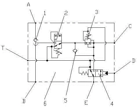
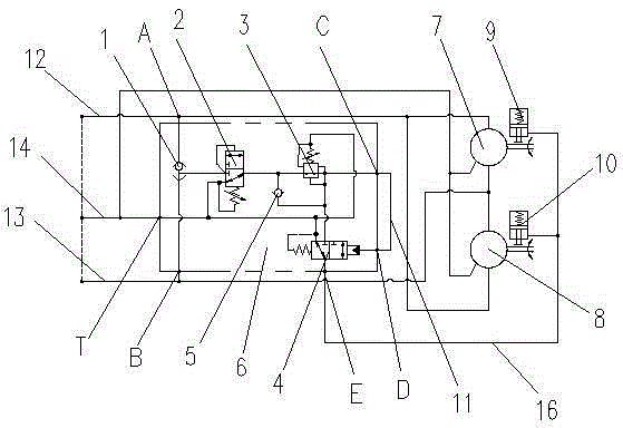
[0022] see figure 1 and figure 2 , when the control oil port C and the control oil port D on the valve body 6 are communicated with the connecting oil line 11, the hydraulic oil entering from the No. 1 oil inlet line 12 and the No. And the oil inlet B flows into the shuttle valve 1, the shuttle valve 1 is opened under the action of the pressure difference, and then flows through the connecting oil circuit 11 through the hydraulic reversing valve 2, the pressure relief valve 3 and enters the pilot fluid through the control oil port C In the dynamic reversing valve 4, the pilot hydraulic reversing valve 4 is opened under the push of hydraulic oil, and the brake oil port E on the valve body 6 is connected with the brake oil circuit 16, and drives No. 1 brake device 9 and No. 2 brake device respectively. 10. Automatically release the brake on No. 1 injection head motor 7 and No. 2 injection head motor 8.

...

Embodiment 2

[0025] Control oil port C and control oil port D disconnected state

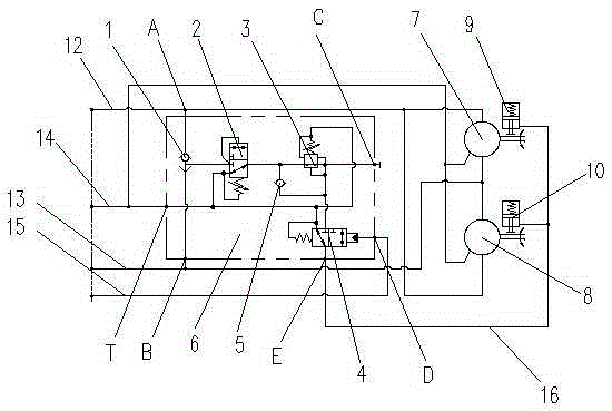
[0026] see figure 1 and image 3 , the control oil port D on the valve body 6 is connected with the external oil line 15, when the hydraulic oil entering the No. 1, the shuttle valve 1 opens under the action of the pressure difference and enters the hydraulic reversing valve 2 and pressure relief valve 3. Since the control oil port C on the valve body 6 is closed, the hydraulic oil reaches the pilot hydraulic reversing valve. In the valve 4, after oil is supplied to the external oil circuit 15 connected with the control oil port D at this time, the pilot hydraulic reversing valve 4 is opened and communicated with the brake oil circuit 16 through the brake oil port E on the valve body 6, Drive No. 1 brake device 9 and No. 2 brake device 10 respectively, and automatically release the brake on No. 1 injection head motor 7 and No. 2 injection head motor 8 .

[0027] When the pressure of the oil inlet A and th...


PUM


Abstract

The invention provides a combined brake control device. A shuttle valve, a hydraulic change-over valve, a pressure reducing overflow valve, a pilot hydraulic change-over valve and a one-way valve are arranged in a valve body of the device, the oil outlet of the shuttle valve is communicated with the oil inlet of the hydraulic change-over valve, the oil outlet of the hydraulic change-over valve is communicated with the oil inlet of the pressure reducing overflow valve, the oil outlet of the pressure reducing overflow valve is communicated with the oil inlet of the pilot hydraulic change-over valve, the oil inlet of the pilot hydraulic change-over valve is connected with the oil inlet of the one-way valve, the oil inlet of the shuttle valve is respectively communicated with an oil inlet A and an oil inlet B on the valve body, and the oil outlet of the pilot hydraulic change-over valve is communicated with a brake oil port E. The device adopts the combination of various valve bodies for control, after entering into the valve bodies, hydraulic oil can directly reach a brake opening through the pilot hydraulic change-over valve, the brake releasing speed is fast, and the brake releasing is sensitive.

Description

technical field [0001] The invention relates to the field of petroleum supporting equipment, in particular to a combined brake control device. Background technique [0002] When the coiled tubing equipment is in operation in an oilfield enterprise, the oil pipe is mainly controlled by operating the injection head to raise and lower the tubing. The injection head brake is a very important part of the injection head control and other auxiliary equipment. During the working process of the injection head, it is necessary to ensure the safety and reliability of the brake device of the injection head, especially when the tubing is lowered into the well and the suspended load is relatively deep, the equipment needs to be used for other operations in the well or to stop the lifting and lowering operations in case of emergency At this time, it is necessary to ensure that the injection head can hold the oil pipe without loosening. At this time, the brake of the injection head needs t...

Claims


Application Information

Patent Timeline
Patent Type & Authority Applications(China)
IPC IPC(8): F16D65/14F15B11/16F15B13/08F16D121/04
CPCF15B11/16F15B13/08F16D65/14F16D2121/04
Inventor 孙仁俊康丽梅刘燕孙晓明
Owner 中石化四机石油机械有限公司
Why Eureka
Try Eureka