Traction device and rail car

A traction device and traction pin technology, applied in the field of rail car traction, can solve the problems of affecting the transmission of traction force and braking force, easy to produce impact, inconvenient for rescue and transition, etc., and achieve the effect of effective transmission and simplified structure

Active Publication Date: 2011-04-20
CRRC YONGJI ELECTRIC CO LTD
View PDF5 Cites 27 Cited by
  • Summary
  • Abstract
  • Description
  • Claims
  • Application Information

AI Technical Summary

Problems solved by technology

[0005] However, there are certain defects in the traction device of the above-mentioned structure: First, because the pin body 12 is a rigid structure, it needs to be carried by bearings, so the gap between the pin body 12 and the bearing is prone to impact, thus affecting the traction force and braking force In addition, there are components such as crank arms, pin bodies, and rods, and the structure is relatively complicated; in addition, the traditional way of connecting the traction device, because the connected rods cannot bear the weight of the bogie itself, makes the bogie and the car body It cannot be directly hoisted as a whole, and it is inconvenient to rescue and transfer after derailment

Method used


Image

  • Traction device and rail car
  • Traction device and rail car
  • Traction device and rail car

Examples


Embodiment Construction

[0033] The technical solutions of the embodiments of the present invention will be further described below in conjunction with the accompanying drawings and specific embodiments.

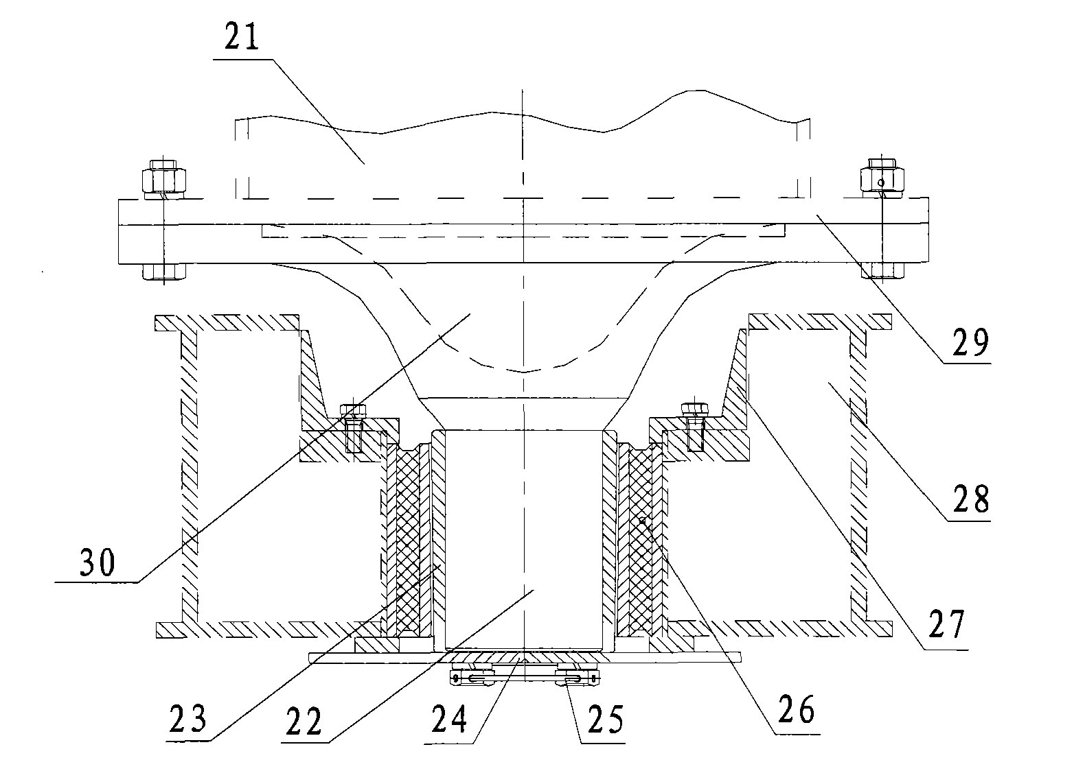
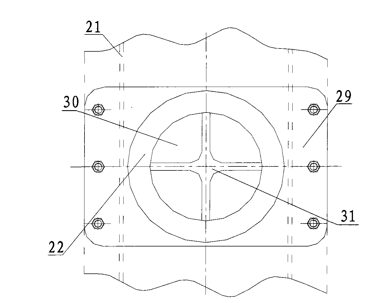
[0034] figure 2 Schematic diagram of the structure of the traction device provided by the embodiment of the present invention, image 3 for figure 2 Top view of the towing device. Such as figure 2 As shown, the traction device can include a vehicle body fixing part 29, an alloy bushing 23, a rubber traction pin joint 26, a traction pin 22 and a bogie fixing part 27, wherein the vehicle body fixing part 29 is used to connect with the vehicle body drawing beam 21 For fixed connection, at least one traction pin 22 may be provided on the side of the vehicle body fixing member 29 away from the vehicle body. In practical applications, the number of traction devices on each vehicle body can be two sets, and in each set of traction devices, one or more traction pins 22 can be set on the side of the v...


PUM


Abstract

The invention provides a traction device and a rail car. The traction device comprises a car body fastener, an alloy bushing, a rubber traction pin joint and a bogie fastener, wherein the car body fastener is fixedly connected with a car body traction beam, and at least one traction pin is arranged at one side of the car body fastener, which is far from a car body; the alloy bushing is sheathed outside the traction pin and fixedly connected with the traction pin; the rubber traction pin joint is sheathed outside the alloy bushing, and the rubber traction pin joint orderly comprises an outer wall rigid plate and a rubber layer from the inside to the outeside; and the bogie fastener is fixedly connected with a bogie traction box and fixedly connected with the outer wall rigid plate of the rubber traction pin joint. Due to the adoption of the technical scheme, the invention simplifies the structure and effectively transmits traction force and brake force.

Description

technical field [0001] The invention relates to rail car traction technology, in particular to a traction device and a rail car. Background technique [0002] Rail cars are mainly used for the transportation of construction materials and personnel during railway construction and maintenance. It can also be used for shunting operations on the lines in the depot and on the main line, or the rescue traction of accident trains, the transportation of equipment and materials, and the traction operations of other unpowered rail vehicles. [0003] The traction device is an important part installed between the car body and the bogie of the rail car to transmit the traction force of the rail car, the braking force, and the impact force during operation. When the electric transmission rail car is working, the power transmission path is: traction motor → wheel axle box → bogie frame → traction device between the car body and bogie → coupler → towed object. Therefore, the basic require...

Claims


Application Information

Patent Timeline
Patent Type & Authority Applications(China)
IPC IPC(8): B61G9/06
Inventor 蔡尚松
Owner CRRC YONGJI ELECTRIC CO LTD
Why Eureka
Try Eureka