
Hydraulic pressure revolving shaft device

A rotating shaft and hydraulic technology, applied in the direction of fluid pressure actuating devices, etc., can solve the problems of reducing the service life of the rotating shaft, generating noise, affecting users, etc., and achieving the effect of solving the problem of non-durability, noise generation, and friction elimination.

Inactive Publication Date: 2013-04-24
HONG FU JIN PRECISION IND (SHENZHEN) CO LTD +1
View PDF4 Cites 0 Cited by
  • Summary
  • Abstract
  • Description
  • Claims
  • Application Information

AI Technical Summary

Problems solved by technology

[0002] For clamshell electronic devices, such as notebook computers, the connection between the cover and the main body requires a rotating shaft, and during the rotation of the notebook computer, the existing design of the rotating shaft will generate friction, reducing the service life of the rotating shaft, and it will also generate noise that affects users

Method used


Image

  • Hydraulic pressure revolving shaft device
  • Hydraulic pressure revolving shaft device
  • Hydraulic pressure revolving shaft device

Examples


Embodiment Construction

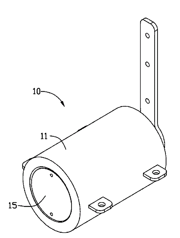
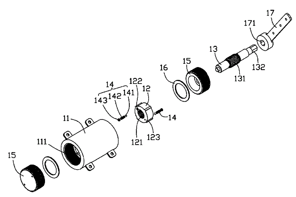
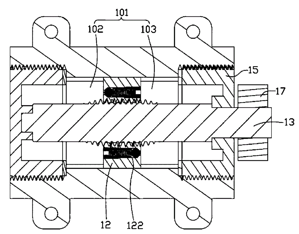
[0011] Please refer to Figure 1 to Figure 3 , which discloses the hydraulic shaft device 10 according to the first embodiment of the present invention. The rotating shaft device 10 includes a casing 11 , a piston 12 , a transmission shaft 13 , an elastic block 14 and a bearing 15 . The bearings 15 are mounted on both ends of the housing 11 and form a sealed chamber 101 with the housing 11. The sealed chamber 101 is filled with liquid. The piston 12 divides the sealed chamber 101 into a first chamber 102 and a second chamber 103. The transmission shaft 13 is mounted on the piston 12 and passes through the sealed chamber 101.

[0012] The shell 11 is cylindrical, and the inner surface of the shell 11 is formed with a plurality of longitudinal guide grooves 111 along the axial direction, and the two ends of the inner surface of the shell 11 are threaded, and the circumferential surface of the shell 11 is provided with a plurality of fixed A member 113, and a fixing hole is for...


PUM


Abstract

The invention provides a hydraulic pressure revolving shaft, which comprises a shell, a piston, a transmission shaft, at least two passages and elastic plugging parts, wherein a sealing cavity is formed in the shell; liquid is filled in the sealing cavity; the piston divides the sealing cavity into a first chamber and a second chamber; the transmission shaft passes through the piston and is screwed with the piston, and is extended out of the shell; the at least two passages are communicated with the first chamber and the second chamber; the size of one end of each of the passages is reduced gradually and the orientations of the passages are opposite to each other; the elastic plugging parts are used for plugging the passages; when the rotating force applied to the transmission shaft is smaller than a predetermined value, the passages are plugged, and the transmission shaft cannot rotate; and when the rotating force applied to the transmission shaft is greater than the predetermined value, the plugging parts are compressed, the passages are opened and the transmission shaft rotates.

Description

technical field [0001] The invention relates to a rotating shaft device. Background technique [0002] For clamshell electronic devices, such as notebook computers, the connection between the cover and the main body requires a rotating shaft, and during the rotation of the notebook computer, the existing design of the rotating shaft will generate friction, reducing the service life of the rotating shaft, and it will also Generate noise and affect users. Contents of the invention [0003] In order to solve the above technical problems, it is necessary to provide an improved rotating shaft device, which can solve the above problems. [0004] The hydraulic rotating shaft includes a casing, and a sealed cavity is formed in the casing, and the sealed cavity is filled with liquid. It is characterized in that the sealed cavity is filled with liquid. The piston in the second chamber passes through the piston, and the piston is screwed and extends out of the transmission shaft ou...

Claims


Application Information

Patent Timeline
Patent Type & Authority Patents(China)
IPC IPC(8): F15B15/06
Inventor 赖金石
Owner HONG FU JIN PRECISION IND (SHENZHEN) CO LTD
Learn More