Supercharge Your Innovation With Domain-Expert AI Agents!

Welded ball pin, and method for the production thereof

A ball pin, ball technology, applied in the direction of manufacturing tools, welding equipment, connections, etc., can solve the problems of increasing complexity and damage to the concentricity of the ball, and achieve the effect of improving service life, improving load bearing capacity, and reducing weight

Inactive Publication Date: 2013-07-10
RUIA GLOBAL FASTENERS AG
View PDF2 Cites 0 Cited by
  • Summary
  • Abstract
  • Description
  • Claims
  • Application Information

AI Technical Summary

Problems solved by technology

[0005] However, this method has the disadvantage that the concentricity of the sphere is subsequently compromised due to the circumferential weld
However, this also increases complexity, especially when manufacturing the shaft, which has to be provided with individual curved surfaces, wherein also the respective different contact surfaces have to be manufactured when using spheres of different diameters

Method used


Image

  • Welded ball pin, and method for the production thereof
  • Welded ball pin, and method for the production thereof

Examples


Embodiment Construction

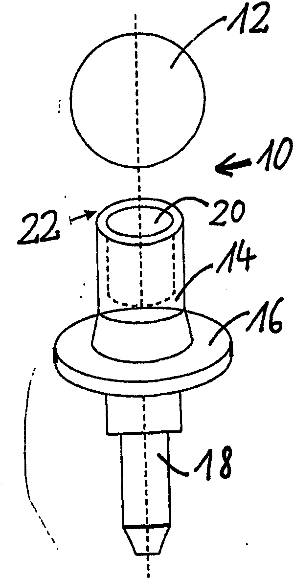
[0026] figure 1 Illustrated is an exploded perspective view of a welded ball pin in accordance with the present invention (before the ball and shaft are welded together).

[0027] The solder ball pin 10 according to the invention comprises a ball 12 which is welded to a shaft 14 . The shaft 14 then transitions into a force sensing element 16 and an externally threaded support 18 . Since these elements may correspond to embodiments in the prior art and do not substantially contribute to the object of the present invention, these elements are not described in detail here.

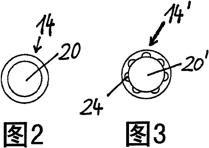
[0028] According to the invention, however, the shaft 14 is configured as a hollow cylinder with an inner cylindrical cavity 20 . Thus, the welding between the ball 12 and the shaft 14 takes place only at the annular portion 22 where the hollow cylindrical shaft 14 is in contact with the ball 12 . Nevertheless, this arrangement is much more durable than the prior art in which a shaft 14 made of solid bar s...


PUM


Abstract

The invention relates to a welded ball pin (10) including a shaft (14; 14′) on which a completely closed ball (12) is welded, wherein the shaft (14; 14′) is configured as a hollow cylinder and an inner wall of the shaft (14′) is provided with grooves (24) extending parallel to a rotation axis of the shaft (14′).

Description

technical field [0001] The present invention relates to solder ball pins and to methods of their manufacture. Background technique [0002] Ball pins are preferably used where one or two components must be movably connected to each other. [0003] Ball pins generally include a ball and a shaft. For welded ball pins, the two parts, the ball and the shaft, are joined by a welding process. In the prior art, shafts are generally made from cylindrical bar stock, with balls welded to the shaft. Based on this geometry, prior art ball pins increase the stresses at the transition between the ball and the shaft and at the weld under alternating bending loads. Thus, in the prior art, there is an increased risk of weld fracture in the transition zone portion, which could lead to complete failure of the solder ball pin. [0004] For such ball pins, previous attempts have been made to prevent fracture of the weld between the ball and the shaft. Thus, for example, DE-OS 2300670 has pr...

Claims


Application Information

Patent Timeline
Patent Type & Authority Patents(China)
IPC IPC(8): B23K31/02
CPCF16C11/0609B23K31/02F16C2226/36Y10T403/477Y10T156/10
Inventor 罗伯特·伯恩盖茨
Owner RUIA GLOBAL FASTENERS AG
Features
  • R&D
  • Intellectual Property
  • Life Sciences
  • Materials
  • Tech Scout
  • Unparalleled Data Quality
  • Higher Quality Content
  • 60% Fewer Hallucinations
Learn More