Hair remover

A hair removal and outer blade technology, applied in metal processing, etc., can solve problems such as noise, increased interference between outer blade and inner blade, and difficulty in bending

Active Publication Date: 2013-12-25
PANASONIC CORP
View PDF2 Cites 1 Cited by
  • Summary
  • Abstract
  • Description
  • Claims
  • Application Information

AI Technical Summary

Problems solved by technology

Thus, it is difficult for the upper part of the outer blade and the inner blade to bend correspondingly
This increases the interference between the outer and inner blades and creates a louder noise

Method used


Image

  • Hair remover
  • Hair remover
  • Hair remover

Examples


Embodiment Construction

[0020] A hair remover according to an embodiment of the present invention will now be described with reference to the accompanying drawings.

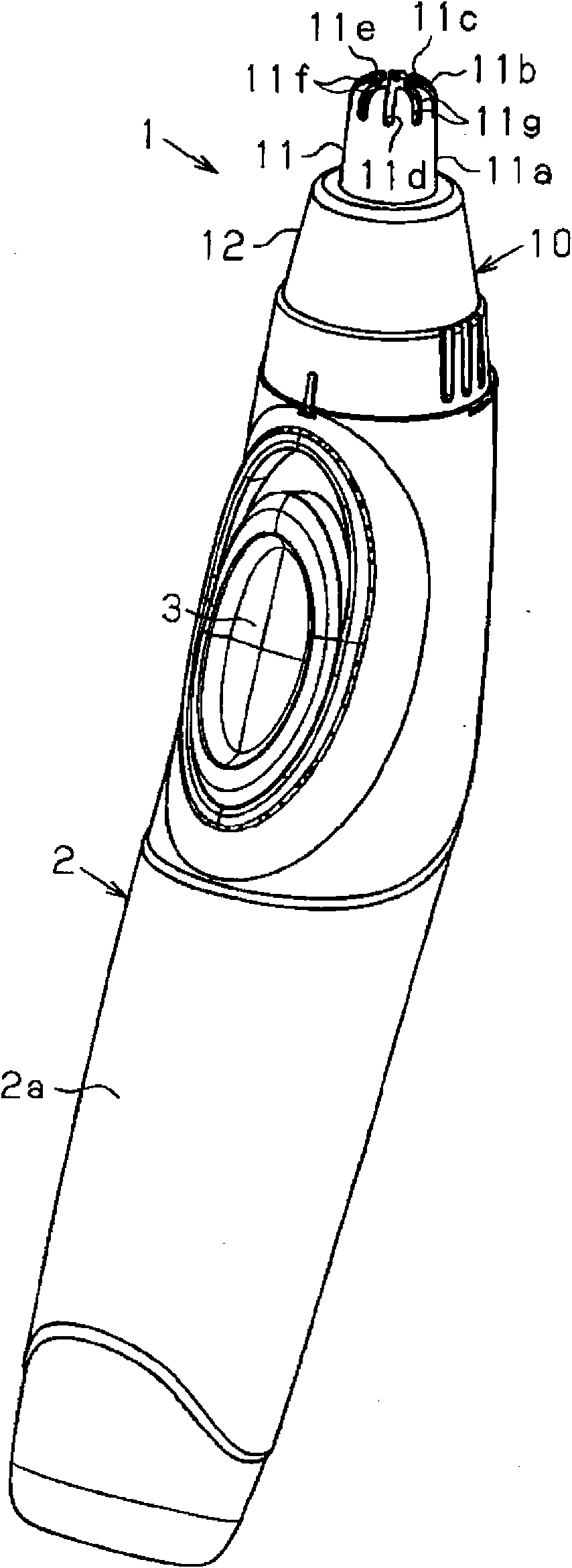
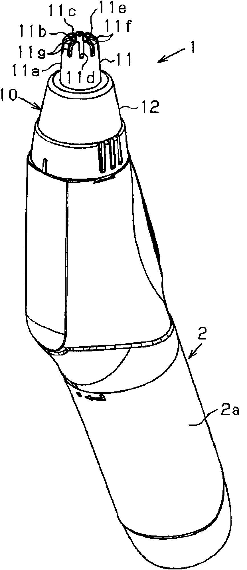
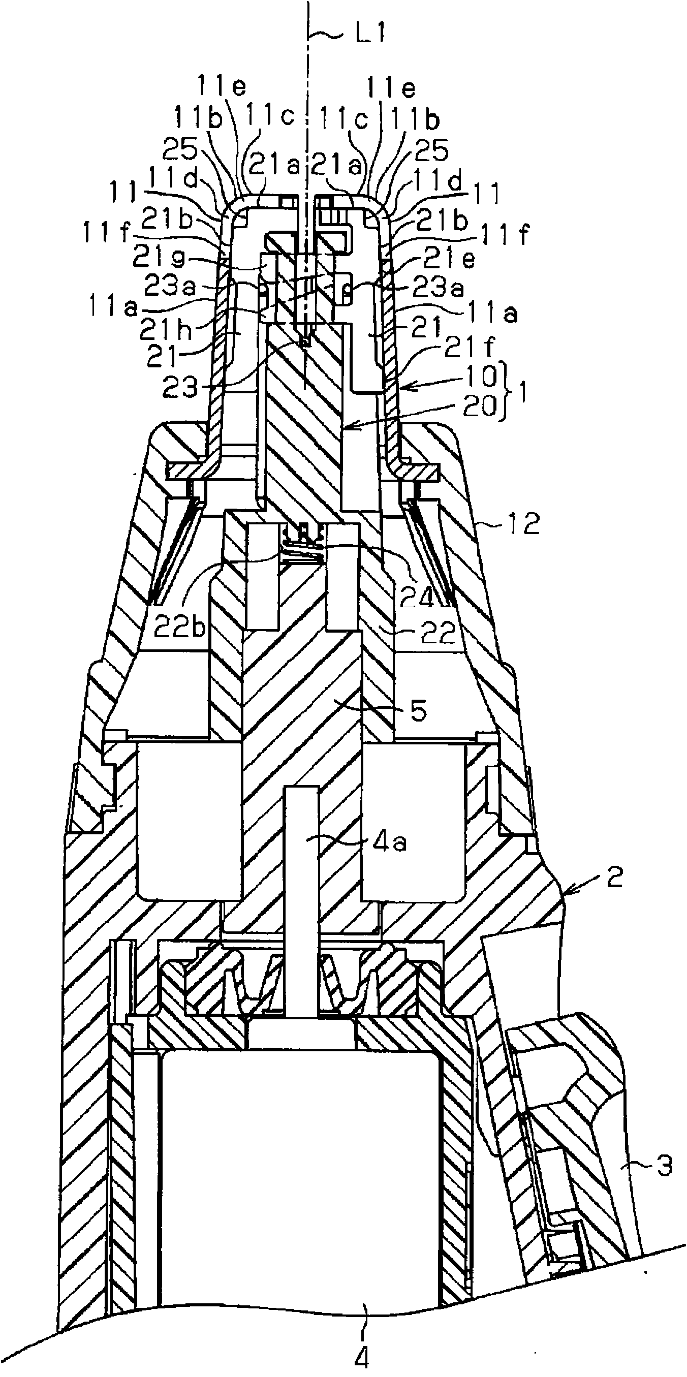
[0021] Figure 1A and 1B A nose hair trimmer is shown used as a hair remover. The overall shape of the nose hair trimmer is cylindrical, and includes a blade unit 1 and a main body 2 connected to the bottom end of the blade unit 1 . Such as image 3 As shown, the blade unit 1 includes an outer blade set 10 and an inner blade set 20 inserted into the outer blade set 10 .

[0022] The main body 2 has a lower portion delimiting a handle 2a. The switch 3 is arranged on the upper side of the handle 2a, and the user operates the switch 3 to turn on or off the nose hair trimmer. The parts of the blade unit 1 and the main body 2 above the handle 2a are inclined with respect to the handle 2a. This shape allows the user to easily insert the outer blade 11 into the nostril while keeping the handle 2a vertical.

[0023] refer to figure 2 ,...


PUM


Abstract

A hair remover including a cylindrical outer blade (11) and an inner blade (21) rotatably accommodated in the outer blade. The outer blade (11) includes a side wall (11a), a bend (11b), and an upper wall (11c) that are continuous with each other. A first cutting edge (11e, 11f) is arranged on the upper wall (11c) and the side wall (11a). The inner blade (21) includes a second cutting edge (21a, 21b) arranged so as to clip hair in cooperation with the first cutting edge (11e, 11f) of the outer blade, The hair remover further includes a relief (25; 25a; 11h; 11i, or 11j) arranged on at least either one of the inner blade and the outer blade to prevent contact between the inner blade (21) and the bend (11b) of the outer blade (11).

Description

[0001] Cross References to Related Applications [0002] This application is based on and claims the benefit of priority from prior Japanese Patent Application No. 2009-220453 filed on September 25, 2009, the contents of which are incorporated herein by reference. technical field [0003] The present invention relates to a hair remover for trimming body hair such as nose hair. Background technique [0004] Japanese Patent Laid-Open No. 7-313241 describes a conventional nose hair trimmer. This nose hair trimmer includes a cylindrical outer blade adapted to be inserted into a nostril and an inner blade accommodated in the outer blade. The drive source drives and rotates the inner blade. This nose hair trimmer cuts the nose hair between the fixed outer blade and the rotating inner blade. In this nose hair trimmer, the outer blade includes a side wall whose upper portion is bent and inwardly curved. Slits extend from the curved upper end of the outer blade toward the sidewa...

Claims


Application Information

Patent Timeline
Patent Type & Authority Patents(China)
IPC IPC(8): B26B19/14
CPCB26B19/148
Inventor 森杉和弘生田利夫
Owner PANASONIC CORP
Why Eureka
Try Eureka