Tension support mechanism of compact spinning device

A tension and support seat technology, applied in spinning machines, textiles and papermaking, drafting equipment, etc., can solve the problems of poor grid tensioning efficiency, unable to fully achieve yarn hairiness strength, and long slack parts, etc. The effect of improving the tensioning efficiency

Inactive Publication Date: 2012-05-23
常州市同和纺织机械制造有限公司
View PDF0 Cites 0 Cited by
  • Summary
  • Abstract
  • Description
  • Claims
  • Application Information

AI Technical Summary

Problems solved by technology

The tension mechanism of this structure is installed on the back of the accumulating roller and is basically placed close to the level. After the fiber strands pass through the drafting device, the lint hairiness and flying flowers in the air and dust will easily cause accumulation of flowers at the tension bracket. The tension support after the flower accumulation is easy to make the grid circle run out of the control range of the tension support, so that the grid circle deviates, so that the fiber strands cannot quickly enter the position of the airflow guide groove, and the fiber strands can only pass through part of the airflow guide groove. , so the fiber strands passed through the pneumatic gathering device cannot fully achieve the required yarn hairiness and its strength
On the other hand, the supporting point of the tension bar of this structure on the mesh ring is closer to the distance where the yarn enters the airflow guide groove, and farther away from the clamping point of the accumulating roller and the control top roller, so that the mesh ring The slack part is long, the grid ring with large manufacturing dimensional tolerance or elongated during use will be axially offset when rotating, and the axially offset grid ring will cause its tension to change or completely break away from the accumulation The clamping point between the roller and the control top roller does not move, so that the fiber strands cannot be gathered according to the design requirements, and the yarn cannot fully meet the required yarn hairiness and strength
[0004] At present, the tension rod is also installed on the oblique lower side of the accumulating roller. The tension rod is equipped with a plurality of limit sliders that limit the axial movement of the grid ring, but the tension rod must be inserted into the two connecting parts. Then it is connected with the collecting tube, which not only requires the connector and the collecting tube to have good manufacturing precision and assembly precision requirements, but also has high requirements for the production of the grid ring
At the same time, since the tension rod is set on the oblique lower side, the efficiency of tensioning the grid ring is poor
In addition, although there is a rib on the limiting slide, the rib is on the side of the loose grid ring, and is not set at the bottom of the limiting slide. Therefore, the limit slide with this structure The stopper cannot effectively control the axial movement of the grid ring, and the grid ring after the axial offset also changes its tension or completely breaks away from the clamping point between the accumulating roller and the control top roller so that it does not move, which affects spinning performance
[0005] The tension rods of the above two structures are all fixed on the tension frame or the connecting piece, and the tension rod cannot be turned over. When the grid circle is separated from the tension rod, the tension rod will quickly rise to the maximum state and make its position higher, so that the cleaning When disassembling and installing the grid ring, the tension mechanism must be pressed one by one to install the grid ring, so the current tension mechanism has the problem of difficulty in installing the grid ring

Method used


Image

  • Tension support mechanism of compact spinning device
  • Tension support mechanism of compact spinning device
  • Tension support mechanism of compact spinning device

Examples


Embodiment Construction

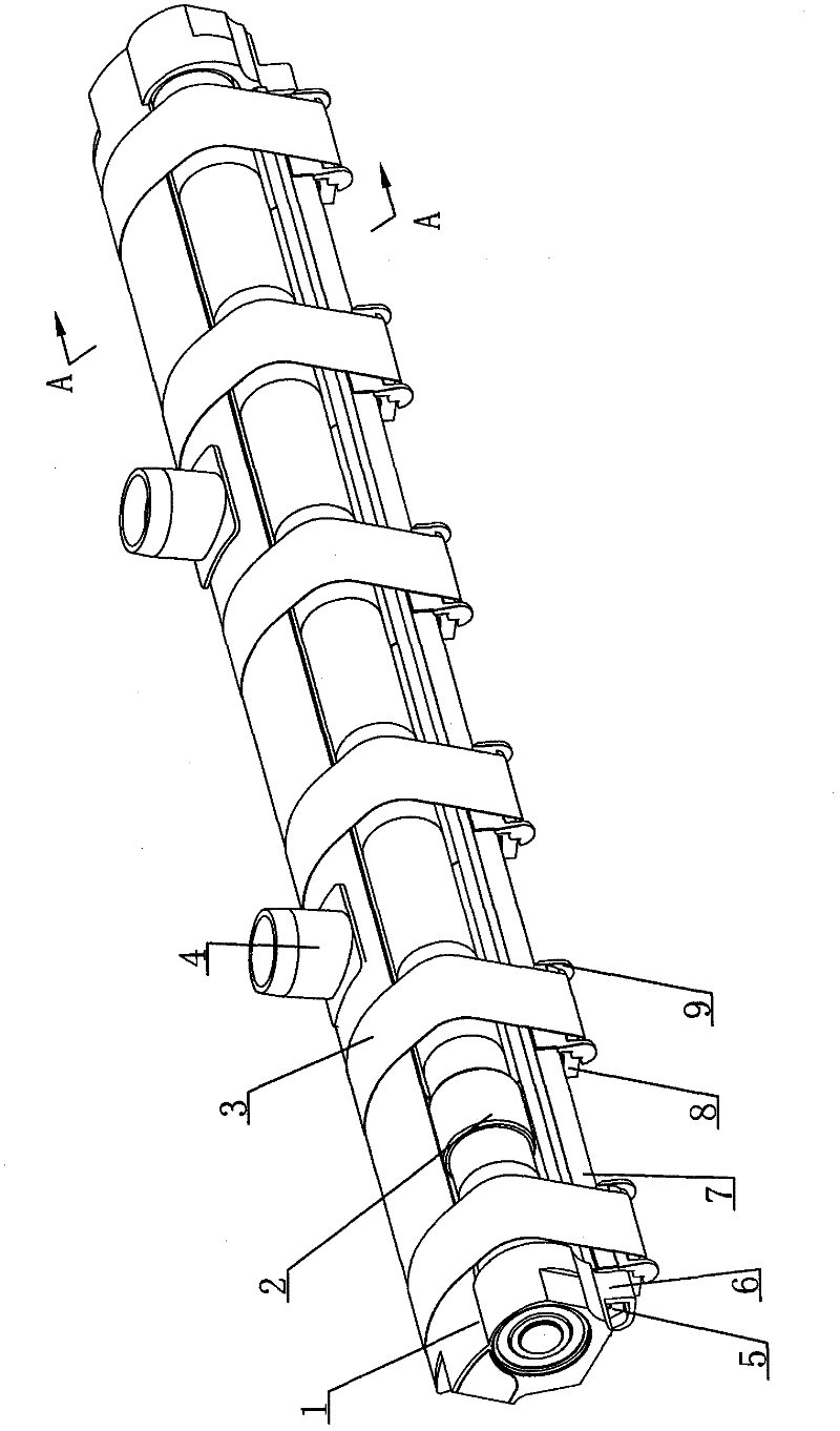
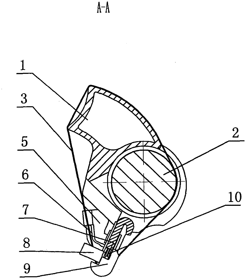
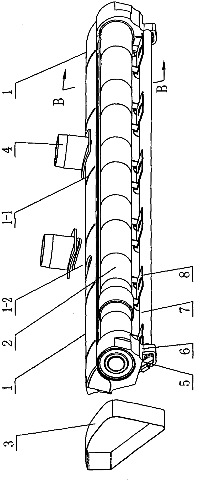
[0024] See Figure 1-13 As shown, the tension support mechanism of the compact spinning device of the present invention includes two tension support seats 6 arranged on the lower side of the negative pressure accumulation tube, a tension support frame and two positioning spring pieces 5, and two tension support seats 6 are provided with installation hole. See Figure 1~5 As shown, the two tension support seats 6 of the present invention are located at the lower side of the negative pressure accumulation pipe 1, the tension support seats 6 are fixed on the bottom of the negative pressure accumulation pipe 1, and the two tension support seats 6 and the negative pressure accumulation pipe 1 are made into an integral structure. At least one suction hole 1-2 and more than three airflow guide grooves 1-1 communicated with the negative pressure chamber are provided on the tube wall of the negative pressure accumulation pipe along the guide surface, and the suction joint 4 is fixed o...


PUM


Abstract

The invention discloses a tension support mechanism of a compact spinning device. The tension support mechanism comprises two tension support seats which are arranged on the lower side of a negative pressure gathering tube, a tension support frame and two positioning spring pieces, wherein the tension support frame comprises a tension rod and more than three limit sliding seats which are transversely arranged along the tension rod at intervals and prop against the lower part of the tension rod through an adjusting spring; the bottom of each limit sliding seat is provided with a stop block; a connection surface of the two positioning spring pieces is connected with the two tension support seats respectively; an adjustment mounting surface of the two positioning spring pieces is compressively jointed with two ends of the tension rod respectively; the two ends of the tension rod are arranged in mounting holes of the two tension support seats; and the adjustment mounting surface of the two positioning spring pieces is provided with a fitting surface and an inner protrusion. The tension rod can be arranged on the two tension support seats through the two positioning spring pieces, and a lattice apron is convenient to assemble and disassemble and can be reliably limited by turning the tension rod.

Description

technical field [0001] The invention relates to a tension support mechanism of a compact spinning device, which belongs to the field of pneumatic gathering devices of compact spinning machines. Background technique [0002] In order to eliminate the spinning triangle area in the compact spinning machine, a negative pressure pneumatic gathering device for fiber strand aggregation is added downstream of the main draft. There are multiple airflow guide grooves on the pipe wall of the guide surface of the negative pressure accumulation tube, and the surface of the mesh ring is densely covered with air holes. The multiple mesh rings are respectively set on the airflow guide grooves of the negative pressure accumulation pipe. Make each airflow guiding groove correspond to a fiber whisker. Under the action of negative pressure airflow in the negative pressure collecting tube, the hairiness of the fiber whiskers is gathered on the airflow guiding groove while being rotated and conve...

Claims


Application Information

Patent Timeline
Patent Type & Authority Patents(China)
IPC IPC(8): D01H5/56
Inventor 崔桂生徐建通胡文君
Owner 常州市同和纺织机械制造有限公司
Why Eureka
Try Eureka