
Electric Connector

A technology of electrical connectors and connecting terminals, which is applied in the direction of connections, circuits, and parts of connection devices, and can solve problems such as missing the semi-fitting state of small printed circuit boards

Active Publication Date: 2014-07-30
JST MFG CO LTD
View PDF6 Cites 0 Cited by
  • Summary
  • Abstract
  • Description
  • Claims
  • Application Information

AI Technical Summary

Problems solved by technology

[0011] In addition, in the case of looking down on the main printed circuit board, if it is difficult to distinguish the locked state and the unlocked state of the small printed circuit board connected to the electrical connector, it is also possible to miss the half-embedded state where the small printed circuit board and the electrical connector are not fully fitted. Combined state

Method used


Image

  • Electric Connector
  • Electric Connector
  • Electric Connector

Examples


Embodiment Construction

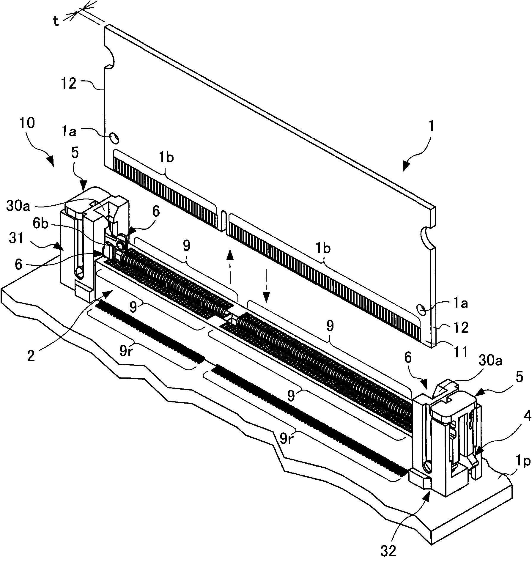
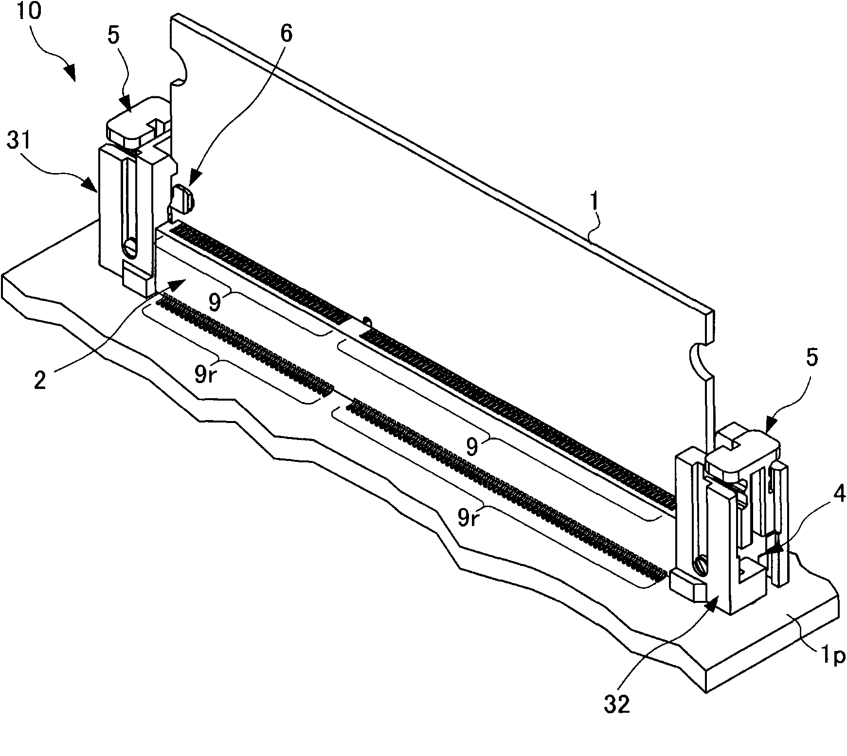
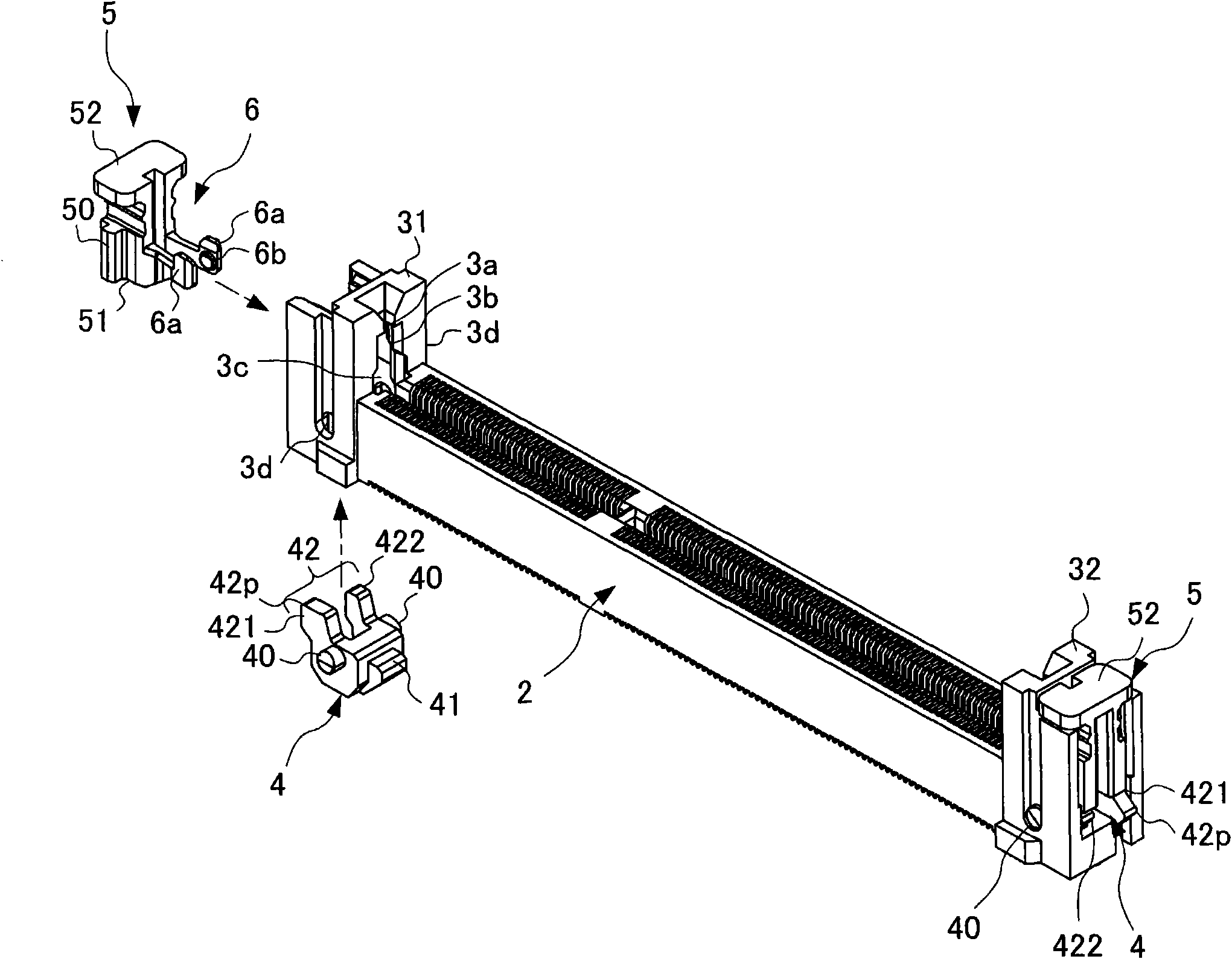
[0054] The present inventors have found that the problem can be solved by using a lever crank that converts the forward motion of the small printed board into rotational motion, and in conjunction with the rotational motion of the lever crank, in the direction opposite to the forward direction of the small printed board. The moving ejector constitutes the locking mechanism. The ejector has a pair of clamp arms that securely lock the small printed circuit board. When the pair of clamp arms fit the small printed circuit board, the lever crank is hidden inside the head. Part of the lever crank protrudes from the head when the clamp arm releases the small printed circuit board. Accordingly, the following new electrical connectors are invented.

[0055] Hereinafter, modes for implementing the present invention will be described with reference to the drawings.

[0056] First, the configuration of an electrical connector according to an embodiment of the present invention will be de...


PUM


Abstract

The invention provides an electric connector capable of preventing half tabling of a printing substrate. The connector (10) is provided with a housing (2), a pair of head parts (31, 32), a pair of lever cranks (4, 4), a pair of ejectors (5, 5), and a pair of clamping arms (6, 6). In a state of performing pressing upon a pressed part (52) and the clamping arms (6) releasing the printing substrate (1), a protruding part (42P) protrudes from the outer wall of the head part (31). The protruding part (42P) can be confirmed from the upper part of the pressed part (52), and a circumstance of releasing the printing substrate (1) can be identified. On the other hand, in a state of the clamping arms (6) tabling the printing substrate (1), the protruding part (42P) is received in the interior of the head part (31). Non-protruding of the protruding part (42P) can be confirmed from the upper part of the pressed part (52) and a circumstance of tabling the printing substrate (1) can be identified.

Description

technical field [0001] The present invention relates to electrical connectors. In particular, it relates to a structure of an electrical connector having a locking mechanism for reliably engaging or releasing a printed circuit board. Background technique [0002] A main printing base on which a CPU is mounted is mounted on a main body such as a personal computer or a server. In addition, small printed circuit boards for the main memory are connected to these main printed circuit boards via electrical connectors. [0003] For example, DDR3 (Double-Date-Rate3, Double Data Rate Three Channels) SDRAM for main memory is a standard of DRAM composed of semiconductor integrated circuits. DDR3 SDRAM has the form of a standardized rectangular small printed circuit board, and has edge connectors at its ends. The DDR3 SDRAM is electrically connected to the main printed substrate by inserting the edge connector into the electrical connector of the main printed substrate. [0004] Gen...

Claims


Application Information

Patent Timeline
Patent Type & Authority Patents(China)
IPC IPC(8): H01R12/71H01R13/629H01R13/639
Inventor 工藤广纪
Owner JST MFG CO LTD
Learn More