Supercharge Your Innovation With Domain-Expert AI Agents!

Hollow mechanical mechanism of arc welding robot wrist

A mechanical mechanism and robot technology, which is applied in the direction of manipulators, arc welding equipment, welding equipment, etc., can solve the problems of difficulty in manufacturing cone-worm mechanisms, inconvenient application, and difficulty in ensuring wrist motion accuracy. It is easy to guarantee wrist motion accuracy and process and manufacture Easy, drive kinematic chain simple effect

Inactive Publication Date: 2012-01-11
HARBIN INST OF TECH
View PDF0 Cites 0 Cited by
  • Summary
  • Abstract
  • Description
  • Claims
  • Application Information

AI Technical Summary

Problems solved by technology

[0003] The purpose of the present invention is to provide a hollow mechanical mechanism for the wrist of an arc welding robot, so as to solve the problems that the hollow mechanism of the wrist of an arc welding robot does not leave a wiring hole, it is inconvenient to use, it is difficult to manufacture a cone-worm mechanism, and it is difficult to guarantee the movement accuracy of the wrist.

Method used


Image

  • Hollow mechanical mechanism of arc welding robot wrist
  • Hollow mechanical mechanism of arc welding robot wrist
  • Hollow mechanical mechanism of arc welding robot wrist

Examples


specific Embodiment approach 1

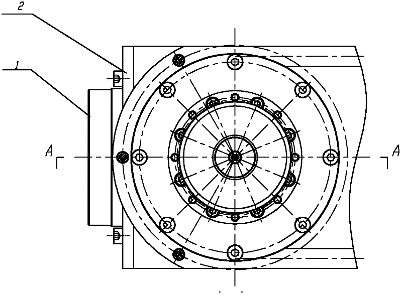
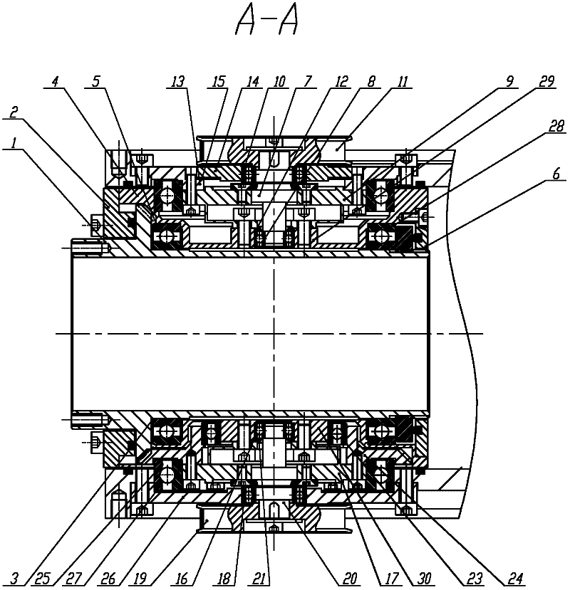
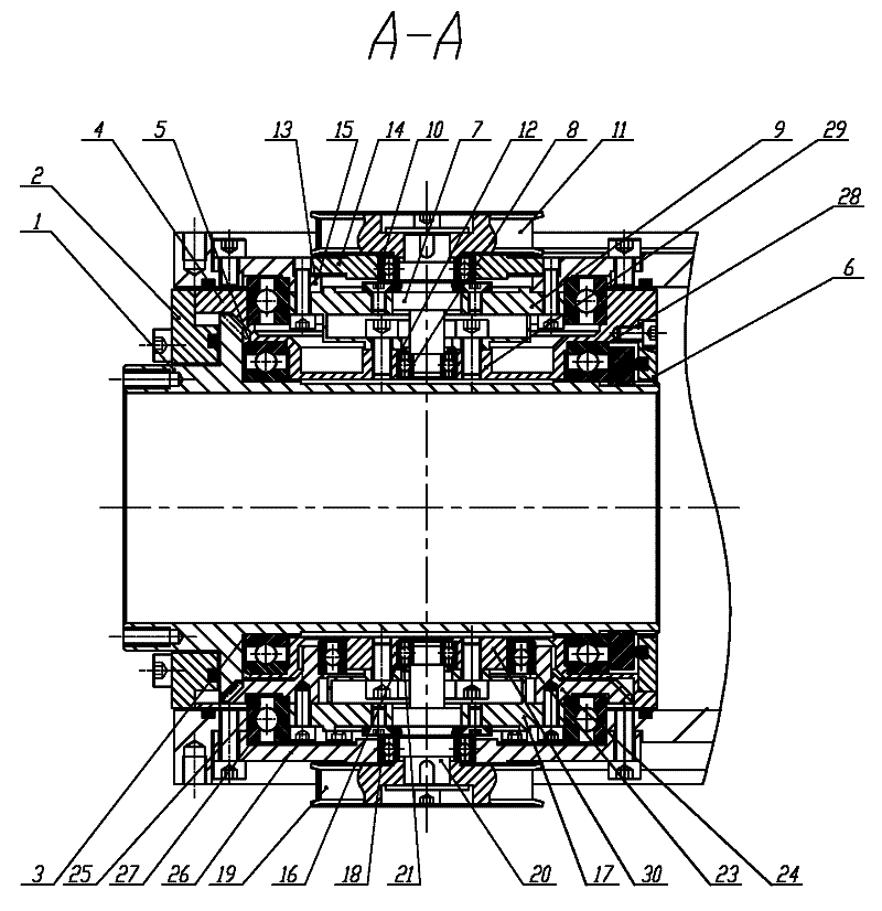
[0009] Specific implementation mode one: combine figure 1 and figure 2 Describe this embodiment, the hollow mechanical mechanism of this embodiment includes hollow gear shaft 1, front gland 2, bevel gear adjustment pad 3, axle seat 4, first bearing 5, rear gland 6, wrist swing motion transmission mechanism, hand Rotating motion transmission mechanism and the eighth bearing 28, the wrist swing motion transmission mechanism includes the first small shaft 7, the second bearing 8, the first harmonic reducer 9, the third bearing 10, the first synchronous toothed belt mechanism 11, the first A positioning ring 12, the first gland 13, the second gland 14, the first adjustment pad 15 and the first shaft sleeve 29, the hand rotation motion transmission mechanism includes the fourth bearing 16, the second harmonic reducer 17, the fifth Bearing 18, second synchronous toothed belt mechanism 19, second small shaft 20, second positioning ring 21, sixth bearing 23, bevel gear 24, seventh b...

specific Embodiment approach 2

[0013] Specific implementation mode two: combination figure 1 Describe this embodiment, the first bearing 5, the second bearing 8, the third bearing 10, the fourth bearing 16, the fifth bearing 18, the sixth bearing 23, the seventh bearing 25 and the eighth bearing 28 in this embodiment are all Ultra-light series bearings can minimize the size of the wrist structure under the premise of ensuring the wrist load. Other components and connections are the same as those in the first embodiment.

specific Embodiment approach 3

[0014] Specific implementation mode three: combination figure 1 The present embodiment will be described. The front end face of the hollow gear shaft 1 of the present embodiment is a common interface end face. This structure is suitable for welding torches of various specifications and has strong versatility. With little or no modification to existing equipment and tools, imported products can be replaced by self-developed robot wrist systems suitable for my country's national conditions, which can reduce costs, facilitate application, and maintain in time.

[0015] Working principle: Connect the welding torch or end effector to the general interface end face of the hollow gear shaft 1. The motion is transmitted to the wrist swing motion transmission mechanism and the hand rotation motion transmission mechanism through the first synchronous toothed belt mechanism and the second synchronous toothed belt mechanism by two servo motors.

[0016] When the motion is wrist swing mo...


PUM


Abstract

The invention discloses a hollow mechanical mechanism of an arc welding robot wrist and relates to a hollow mechanical mechanism of a robot wrist, aiming at solving the problems that routing holes is not left in the hollow structure of an arc welding robot wrist, thus application is inconvenient, a spiroid mechanism is difficult to manufacture and the motion precision of the wrist is difficult to guarantee. In the invention, motions are transmitted to a wrist swinging motion transmission mechanism and a hand rotating motion transmission mechanism through a first synchronous cog belt mechanism and a second synchronous cog belt mechanism by two servo motors; a shaft seat is sleeved on a hollow gear shaft; the front end of the space between the hollow gear shaft and the shaft seat is provided with a first bearing, and the rear end of the space between the hollow gear shaft and the shaft seat is provided with an eighth bearing; the shaft seat is in rotary connection with the hollow gear shaft; a front gland is sleeved at the front end of the hollow gear shaft, and a rear gland is sleeved at the front end of the hollow gear shaft; the rear gland is in detachable connection with the shaft seat; a first small shaft is arranged in a first shaft sleeve; and a second small shaft is sleeved in a second shaft sleeve. The mechanism is applied to arc welding robots.

Description

technical field [0001] The invention relates to a hollow mechanical mechanism of a robot wrist. Background technique [0002] At present, there are two kinds of mechanical structures commonly used in the wrist of arc welding robots in the industry: one is that the six-axis reducer is placed at the end of the wrist, and the appearance is that the connection interface is a cylindrical end surface, which is characterized by a clear transmission line and easy guarantee of wrist movement accuracy. However, there is no wiring hole in the middle of the cylinder, which is inconvenient to use; the other is that the five-axis and six-axis motions are input in parallel by the cone-worm mechanism. Convenient, but the cone-worm mechanism is difficult to manufacture, and the accuracy of wrist movement is difficult to guarantee (the main axis of the robot's wrist swing movement is defined as five axes, and the main axis of the hand rotation movement is defined as six axes). Contents of t...

Claims


Application Information

Patent Timeline
Patent Type & Authority Patents(China)
IPC IPC(8): B23K9/00B25J17/00
Inventor 于殿勇翟万柱李瑞峰
Owner HARBIN INST OF TECH
Features
  • R&D
  • Intellectual Property
  • Life Sciences
  • Materials
  • Tech Scout
  • Unparalleled Data Quality
  • Higher Quality Content
  • 60% Fewer Hallucinations
Learn More