Supercharge Your Innovation With Domain-Expert AI Agents!

Liquid ejection apparatus

A technology of ejecting device and liquid, applied in printing and other directions, can solve the problem of inability to finely adjust the amount of liquid ejected

Inactive Publication Date: 2011-05-04
SEIKO EPSON CORP
View PDF1 Cites 6 Cited by
  • Summary
  • Abstract
  • Description
  • Claims
  • Application Information

AI Technical Summary

Problems solved by technology

However, in this technique, the maximum or minimum voltage of the voltage waveform fluctuates greatly, and it is impossible to finely adjust the ejection amount of the liquid

Method used


Image

  • Liquid ejection apparatus
  • Liquid ejection apparatus
  • Liquid ejection apparatus

Examples


Embodiment Construction

[0044] Next, in order to clarify the contents of the invention of the present application described above, examples will be described in the following order.

[0045] A. Device structure:

[0046] B. The structure of the spray head:

[0047] B-1. Structure of nozzle driving circuit:

[0048] B-2. Generation method of driving voltage waveform:

[0049] C. Adjustment method of injection volume (discharge weight):

[0050] D. Nozzle drive processing:

[0051] E. Variations:

[0052] E-1. The first modified example:

[0053] E-2. The second modified example:

[0054] E-3. The third modified example:

[0055] E-4. Fourth modified example:

[0056] E-5. Fifth modified example:

[0057] A. Device structure:

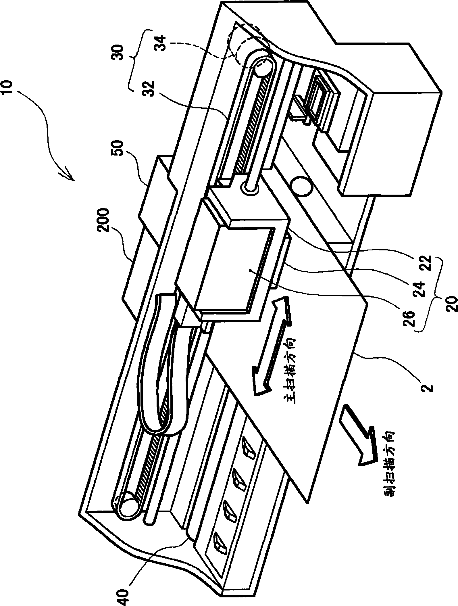
[0058] figure 1 It is an explanatory diagram illustrating an inkjet printer 10 as a liquid ejecting device of this embodiment. The illustrated inkjet printer 10 is composed of a carriage 20 that reciprocates in the main scanning direction and forms ink dots on a prin...


PUM


Abstract

The present invention provides a liquid ejection apparatus. A piezoelectric element for driving an ejection nozzle is switched to connect a plurality of voltages, such that the liquid can be ejected and simultaneously an ejection quantity of the liquid can be regulated. According a drive voltage waveform data, a plurality of standard voltages are switched to connect with the piezoelectric element, so as to eject the liquid from the ejection nozzle. Here, the drive voltage waveform data includes a required time of a waveform section configuring the drive voltage waveform, and a voltage selected from the plurality of reference voltages for the waveform section. When the piezoelectric element is applied by a drive voltage waveform, information related to regulation of the ejection quantity of the liquid is obtained, the required time of the waveform section contained in the drive voltage waveform data is changed according to the information, the drive voltage waveform is then applied to eject the liquid according to the obtained drive voltage waveform data.

Description

technical field [0001] The present invention relates to a technique for ejecting liquid from an ejection nozzle. Background technique [0002] A liquid ejecting device that ejects liquid such as ink using ejection nozzles is known. There are several methods for ejecting liquid from the nozzle, but as a representative method, the following method is widely used: a piezoelectric element is mounted on the nozzle as an actuator, and a predetermined voltage waveform is applied to the piezoelectric element. The ejection nozzle ejects a droplet-shaped liquid. In this mode, by changing the voltage waveform to be applied, the size of the liquid droplet (or the ejection amount of the liquid) can be changed. [0003] Since the piezoelectric element is a capacitive load, when a voltage is applied, charges are accumulated in the piezoelectric element, and a voltage corresponding to the amount of accumulated charge appears as an applied voltage between terminals of the piezoelectric ele...

Claims


Application Information

Patent Timeline
Patent Type & Authority Applications(China)
IPC IPC(8): B41J2/045
CPCB41J2/04591B41J2/04553B41J2/0456B41J2/04581B41J2/0459
Inventor 宫崎新一田端邦夫大岛敦吉野浩行井出典孝
Owner SEIKO EPSON CORP
Features
  • R&D
  • Intellectual Property
  • Life Sciences
  • Materials
  • Tech Scout
  • Unparalleled Data Quality
  • Higher Quality Content
  • 60% Fewer Hallucinations
Learn More