Supercharge Your Innovation With Domain-Expert AI Agents!

Fuel-injection control method and fuel-injection control device

A technology of fuel injection and control method, applied in the directions of fuel injection control, electrical control, engine control, etc., can solve the problem of reduction of fuel storage, difficulty in miniaturization and cost reduction of fuel injection device, and inability to respond to fuel injection demand, etc. question

Inactive Publication Date: 2006-01-18
MIKUNI CORP
View PDF3 Cites 14 Cited by
  • Summary
  • Abstract
  • Description
  • Claims
  • Application Information

AI Technical Summary

Problems solved by technology

[0008] Therefore, although the fuel injection solenoid can be driven by a constant current, or the injector valve opening time delay can be corrected based on the detected value of the injector drive current (coil current) as disclosed in JP-A-2002-4921, due to The solenoid includes the action start time after power-on, and its action characteristics are affected by the temperature. As a result, it is not only impossible to properly respond to the fuel injection demand of the engine, but also because the drive control circuit and software processing are too complicated Difficulty reducing the size and cost of the fuel injection system as a whole
[0009] In addition, in the driving control device of the fuel injection valve for an engine disclosed in Japanese Patent Application Laid-Open No. 8-4575, the temperature of the electromagnetic coil, which is the main factor for changing the operating characteristics, can be indirectly detected based on the measured fuel temperature. However, the temperature of the electromagnetic coil is not necessarily Always consistent with the fuel temperature, the detection equipment for detecting the fuel temperature must be installed in the fuel tank together with the drive control device of the fuel injection valve for the engine, and this part will lead to a decrease in the fuel storage in the fuel tank

Method used


Image

  • Fuel-injection control method and fuel-injection control device
  • Fuel-injection control method and fuel-injection control device
  • Fuel-injection control method and fuel-injection control device

Examples


no. 1 Embodiment approach

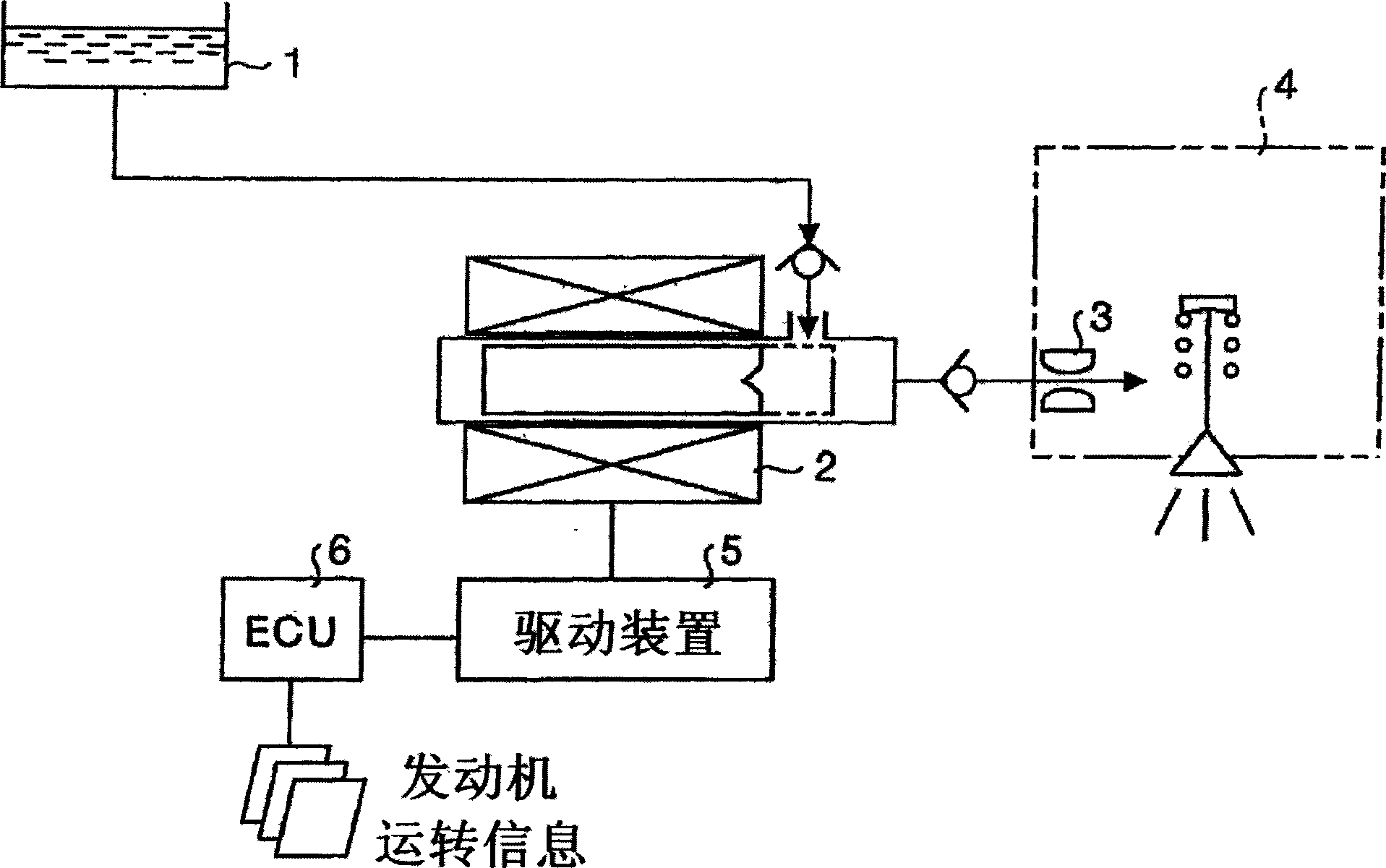
[0053] In the first embodiment of the present invention, the drive pulse current to be output in the next fuel injection cycle is corrected based on the amplitude of the drive pulse output during fuel injection and the actual current integral value after the start of driving the fuel injection solenoid. In this application, the current integral value prestored as data by the present fuel injection control device is referred to as a "reference current integral value", and the detected actual coil current integral value is referred to as an "actual current integral value".

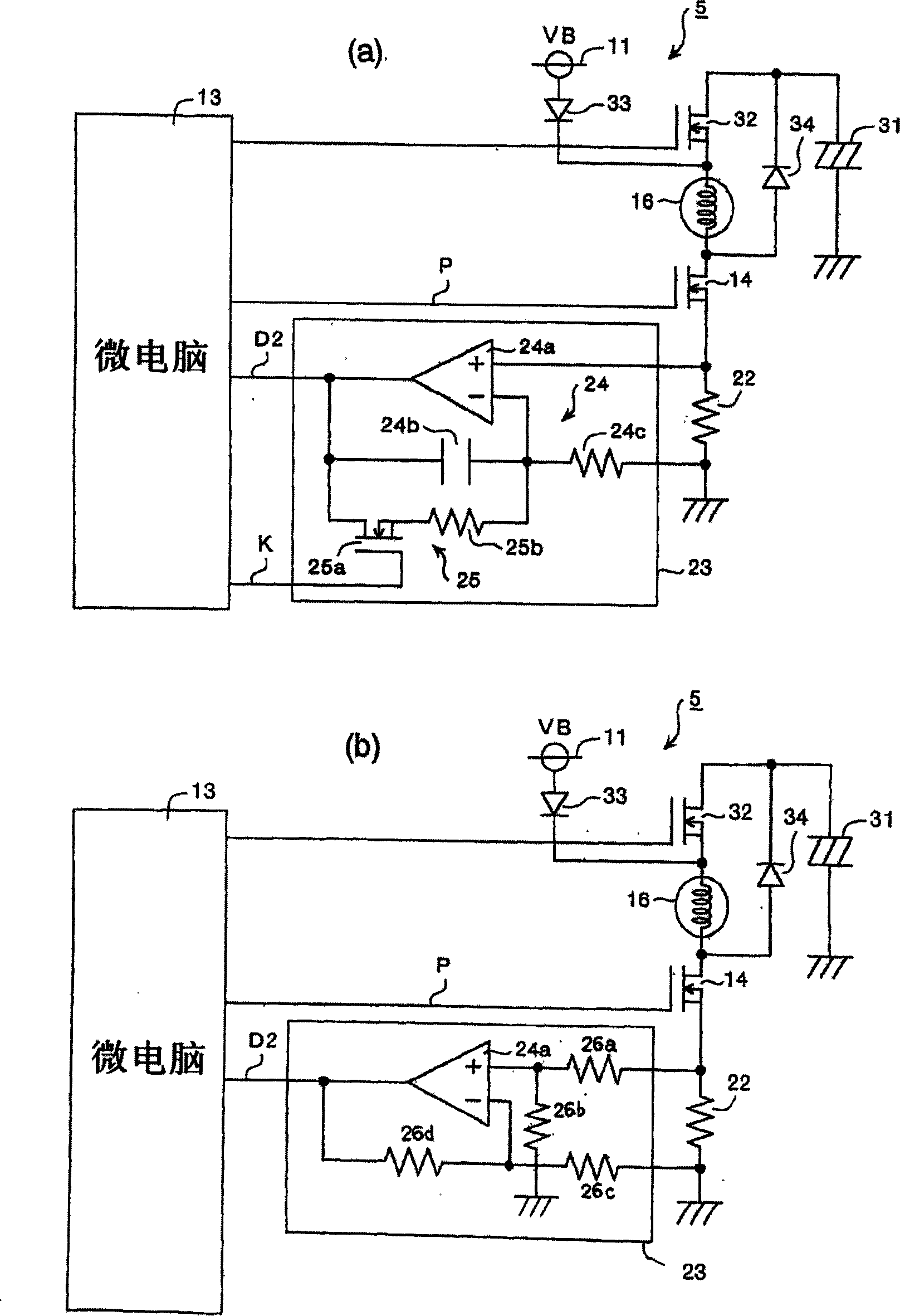
[0054] figure 2 is a specific example of the circuit configuration of the present fuel injection control device.

[0055] exist figure 2 In (a), the solenoid 16 constitutes the electromagnetic fuel injection pump 2 . The drive device 14 for driving this solenoid 16 uses an N-channel FET 14 here. The source of the N-channel FET 14 is connected to the resistor 22 for current detection, and the driving cur...

no. 2 Embodiment approach

[0095] In the second embodiment, the actual current integral value of the coil current flowing through the solenoid is compared with the target current integral value preset for the fuel injection demand amount, and based on the comparison between the actual current integral value and the target current integral value As a result, the magnitude of the drive pulse of the solenoid is corrected, and the solenoid is driven and controlled.

[0096] Therefore, in the second embodiment, the object to be compared with the actual current integral value is replaced by the "reference current integral value preset for the drive pulse amplitude corresponding to the fuel injection demand amount" in the above-mentioned first embodiment. is "the preset target current integral value relative to the fuel injection demand".

[0097] Figure 12 It is a block diagram showing a functional configuration for realizing the fuel injection control method and device according to the second embodiment. ...

no. 3 Embodiment approach

[0104] In the third embodiment, the estimated fuel injection amount corresponding to the actual current integral value of the coil current flowing through the solenoid is compared with the required fuel injection amount, and based on the comparison result of the estimated fuel injection amount and the above-mentioned required fuel injection amount , correct the driving pulse amplitude of the solenoid, and drive and control the solenoid according to the corrected driving pulse amplitude.

[0105] In this third embodiment, the above-mentioned figure 2 (a) or (b) shown in the control circuit. Here, feedback control is performed for correction value calculation, and feedback control is performed to converge the estimated injection flow rate to the target injection amount based on the estimated injection flow rate obtained from the actual current integral value.

[0106] Figure 14 It is a block diagram showing the functional configuration of the fuel injection method and appara...


PUM


Abstract

Accurate fuel-injection control is effected in response to a fuel-injection request of the engine without being influenced by a variation of the voltage of the power supply and a variation of the coil temperature of the fuel-injection solenoid and by other disturbances. The fuel-injection solenoid is driven / controlled according to the actual current integrated value of the coil current after the start of drive of the fuel-injection solenoid. A fuel-injection control method comprises the steps of starting drive of a fuel-injection solenoid, detecting the actual current integrated value of the coil current flowing through the solenoid after the start of the drive, comparing the actual current integrated value with a reference current integrated value predetermined for the drive pulse width of the solenoid corresponding to the requested fuel-injection amount, and correcting the drive pulse width of the solenoid according to the comparison. The solenoid is driven / controlled according to the corrected drive pulse width.

Description

technical field [0001] The present invention relates to an electronically controlled fuel injection control method and device for supplying fuel to an internal combustion engine (hereinafter referred to as "engine"), and specifically relates to the removal of fuel caused by changes in power supply voltage and temperature. A fuel injection control method and a control device for accurately supplying the fuel injection amount required by the engine side due to the influence of changes in the resistance value of the solenoid coil for injection. Background technique [0002] For vehicle engines including two-wheeled vehicles, providing fuel supply at an appropriate timing is an extremely important factor that affects the overall performance of the engine in response to the fuel injection demand that changes from time to time on the engine side. Therefore, an electronically controlled fuel injection device that electronically controls fuel injection of an engine by a microcompute...

Claims


Application Information

Patent Timeline
Patent Type & Authority Applications(China)
IPC IPC(8): F02D41/20
CPCF02D2041/2058F02D41/20F02D2041/2065F02D2041/2027
Inventor 早川邦彦
Owner MIKUNI CORP
Features
  • R&D
  • Intellectual Property
  • Life Sciences
  • Materials
  • Tech Scout
  • Unparalleled Data Quality
  • Higher Quality Content
  • 60% Fewer Hallucinations
Learn More