Communication network realized by network architecture based on separation of control surfaces and media surface
A technology of network architecture and communication network, applied in wireless communication, network data management, network traffic/resource management, etc.
- Summary
- Abstract
- Description
- Claims
- Application Information
AI Technical Summary
Problems solved by technology
Method used
Image
Examples
Embodiment 1
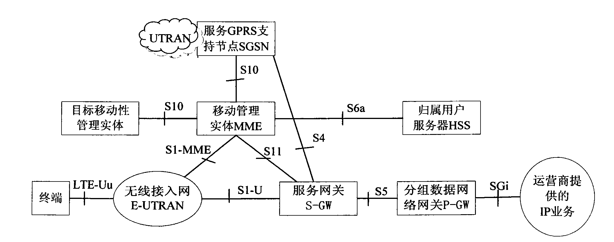
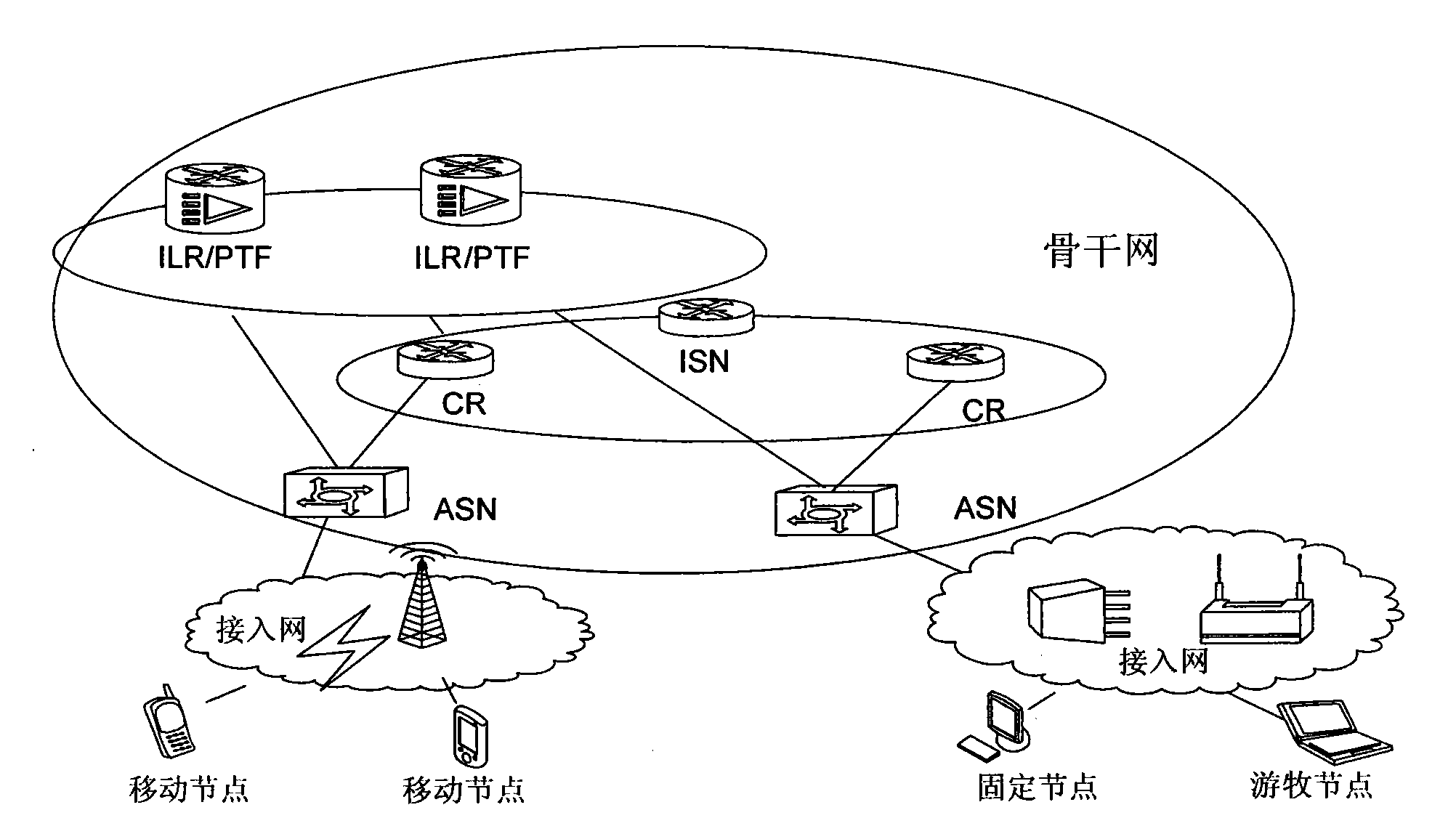
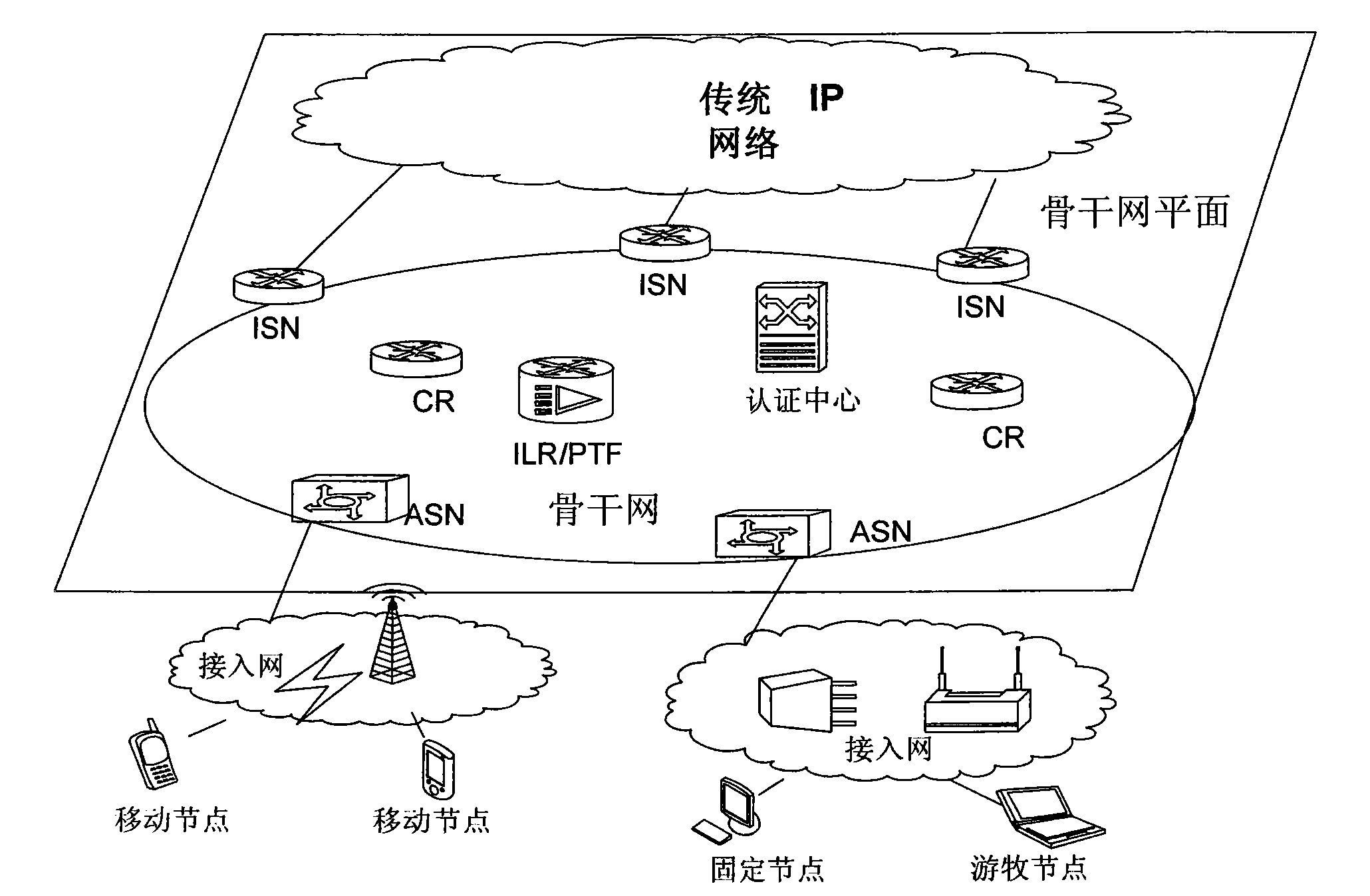
[0234] The SILSN architecture implemented based on the EPS system architecture in this embodiment is as follows: Figure 2a As shown in the figure, the main network elements in the architecture network and the connection interfaces between each network element are shown in the figure. The access network part of the SILSN architecture is mainly realized by the wireless access network in the EPS system, and the Mobility Management Entity (MME), S-GW and the upgraded P-GW in the EPS system jointly realize the functions to be completed by the ASN. At the same time, network elements such as ILR, PTF, and ISN with interfaces to the P-GW are added. These network elements are logical network elements and can be co-located with existing network elements in physical entities. The generalized forwarding plane supports RID routing. packet data network implementation.
[0235] In the SILSN architecture implemented based on the EPS system architecture in this embodiment, there is a signali...
Embodiment 2
[0318] The SILSN architecture implemented based on the EPS system architecture in this embodiment is as follows: Figure 3a and 3b As shown in the figure, the main network elements of the architecture network and the connection interfaces between the network elements are shown in the figure. The access network part of the SILSN architecture is mainly realized by the wireless access network in the EPS system. The S-GW in the EPS system, the upgraded P-GW and the mobility management entity jointly realize the functions to be completed by the ASN. At the same time, network elements such as ILR, PTF, and ISN that have interfaces with the P-GW are added. These network elements are logical network elements, which can be co-located with existing network elements in physical entities, and the generalized forwarding plane can be realized by a packet data network supporting RID routing.
[0319] In this embodiment, there are signaling interfaces between the ILR and the P-GW and betwee...
Embodiment 3
[0403] The SILSN architecture implemented based on the EPS system architecture in this embodiment is as follows: Figure 4a and 4b As shown in the figure, the main network elements of the architecture network and the connection interfaces between the network elements are shown in the figure. There is no signaling interface between the P-GW and the ILR, but there is a signaling interface between the MME and the ILR.
[0404] The access network part of the SILSN architecture is mainly implemented by the wireless access network in the EPS system, and the S-GW in the EPS system, the upgraded P-GW, and MME jointly realize the functions to be completed by the ASN. At the same time, network elements such as PTF and ISN that have interfaces with the P-GW, and ILRs that have signaling interfaces with the MME are added. These network elements are logical network elements, which can be co-located with existing network elements in physical entities, and the generalized forwarding plane ...
PUM
 Abstract
Description
Claims
Application Information
 - R&D
- Intellectual Property
- Life Sciences
- Materials
- Tech Scout
- Unparalleled Data Quality
- Higher Quality Content
- 60% Fewer Hallucinations
Browse by: Latest US Patents, China's latest patents, Technical Efficacy Thesaurus, Application Domain, Technology Topic, Popular Technical Reports.
© 2025 PatSnap. All rights reserved.Legal|Privacy policy|Modern Slavery Act Transparency Statement|Sitemap|About US| Contact US: help@patsnap.com


