
Communication network realized by network architecture based on separation of control surfaces and media surface

A communication network and network architecture technology, applied in wireless communication, network data management, network traffic/resource management, etc.

Inactive Publication Date: 2011-05-04
ZTE CORP
View PDF3 Cites 44 Cited by
  • Summary
  • Abstract
  • Description
  • Claims
  • Application Information

AI Technical Summary

Problems solved by technology

In the prior art, there is no solution based on a network architecture that separates the control plane and the media plane to realize a communication network that separates identity and location

Method used


Image

  • Communication network realized by network architecture based on separation of control surfaces and media surface
  • Communication network realized by network architecture based on separation of control surfaces and media surface
  • Communication network realized by network architecture based on separation of control surfaces and media surface

Examples


Embodiment 1

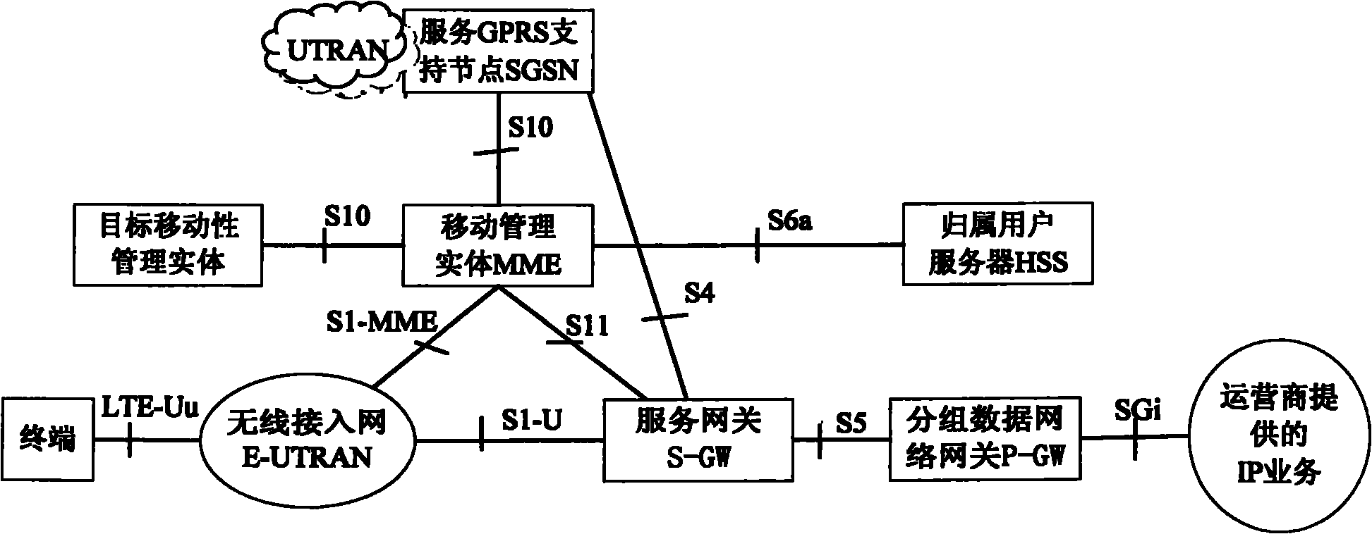
[0233] The SILSN architecture implemented based on the EPS system architecture in this embodiment is as follows: Figure 2a As shown in the figure, the main network elements in the architecture network and the connection interfaces between each network element are shown in the figure. The access network part of the SILSN architecture is mainly realized by the wireless access network in the EPS system, and the Mobility Management Entity (MME), S-GW and the upgraded P-GW in the EPS system jointly realize the functions to be completed by the ASN. At the same time, network elements such as ILR, PTF, and ISN with interfaces to the P-GW are added. These network elements are logical network elements and can be co-located with existing network elements in physical entities. The generalized forwarding plane supports RID routing. packet data network implementation.

[0234] In the SILSN architecture implemented based on the EPS system architecture in this embodiment, there is a signali...

Embodiment 2

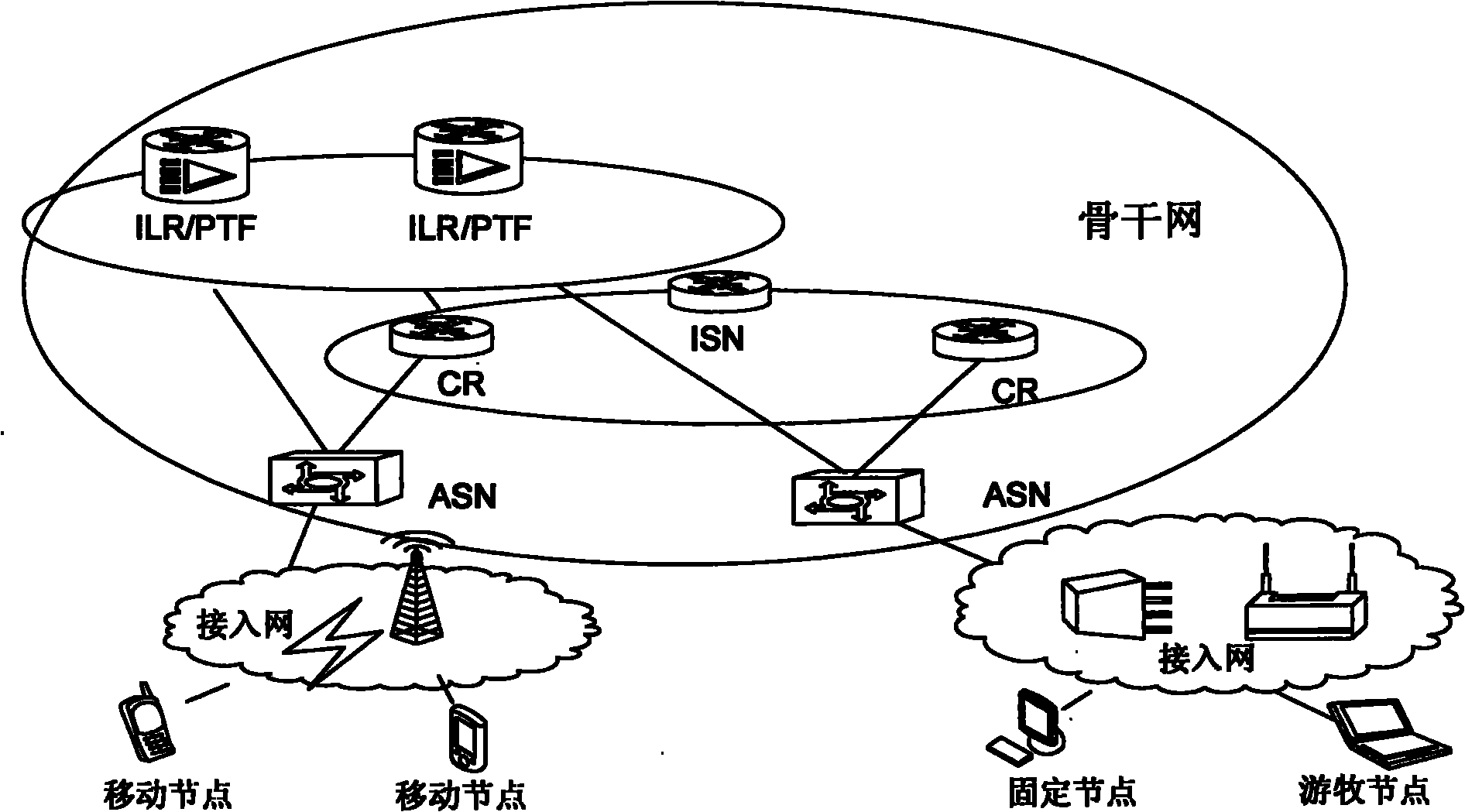
[0317] The SILSN architecture implemented based on the EPS system architecture in this embodiment is as follows: Figure 3a with 3b As shown in the figure, the main network elements of the architecture network and the connection interfaces between the network elements are shown in the figure. The access network part of the SILSN architecture is mainly realized by the wireless access network in the EPS system. The S-GW in the EPS system, the upgraded P-GW and the mobility management entity jointly realize the functions to be completed by the ASN. At the same time, network elements such as ILR, PTF, and ISN that have interfaces with the P-GW are added. These network elements are logical network elements, which can be co-located with existing network elements in physical entities, and the generalized forwarding plane can be realized by a packet data network supporting RID routing.

[0318] In this embodiment, there are signaling interfaces between the ILR and the P-GW and betwe...

Embodiment 3

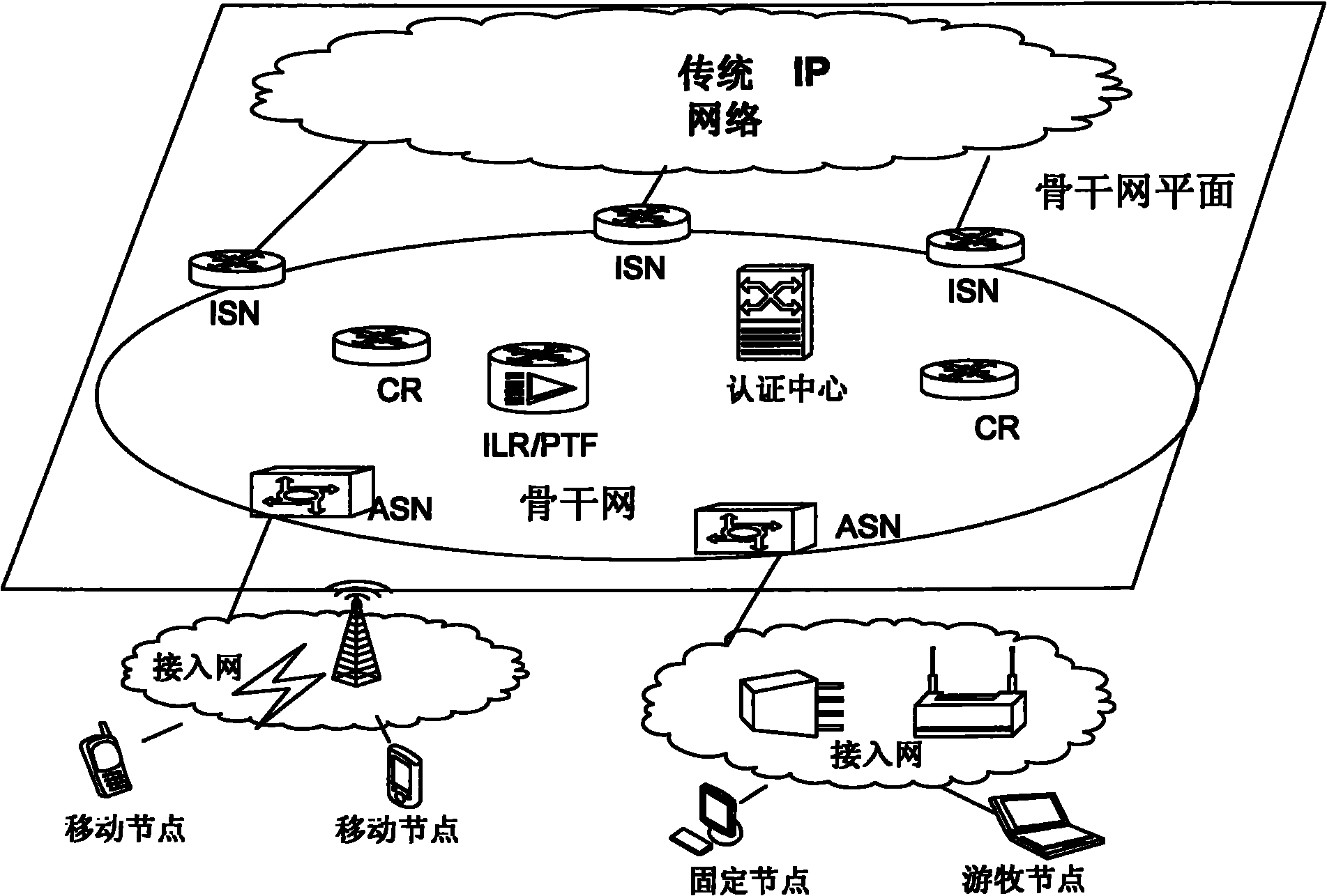
[0402] The SILSN architecture implemented based on the EPS system architecture in this embodiment is as follows: Figure 4a with 4b As shown in the figure, the main network elements of the architecture network and the connection interfaces between the network elements are shown in the figure. There is no signaling interface between the P-GW and the ILR, but there is a signaling interface between the MME and the ILR.

[0403] The access network part of the SILSN architecture is mainly implemented by the wireless access network in the EPS system, and the S-GW in the EPS system, the upgraded P-GW, and MME jointly realize the functions to be completed by the ASN. At the same time, network elements such as PTF and ISN that have interfaces with the P-GW, and ILRs that have signaling interfaces with the MME are added. These network elements are logical network elements, which can be co-located with existing network elements in physical entities, and the generalized forwarding plane...


PUM


Abstract

The invention relates to a communication network realized by a network architecture based on the separation of control surfaces and media surface. The communication network comprises a radio access network, an access node which is connected between the radio access network and a packet data network and is used for data switching, and a mobility management node connected with the access node and the radio access network. The communication network also comprises an identity location register (ILR)and the packet data network which are connected with the access node, wherein the access node provides an access service for a terminal, distributes a route mart directing to the access node for the terminal, maintains the mapping information of the terminal and a correspondence node, registers on an ILR in the terminal location, unregisters and queries the RID of the terminal and realizes the routing and forwarding of the data message; the ILR is used for receiving a registration request and an unregistration request of the ILR home user terminal, maintaining the AID-RID mapping information of the home user terminal and returning the RID corresponding to the AID of the terminal in the request to the party sending a query request after receiving the search request about the RID of the terminal. The communication network can avoid alternate routing and does not change the application context of the terminal.

Description

technical field [0001] The present invention relates to a network architecture in the field of communication technology, in particular to a communication network realized based on a network architecture in which a control plane and a media plane are separated. Background technique [0002] The 3rd Generation Partnership Project (3rd Generation Partnership Project, referred to as 3GPP) evolved packet system (referred to as EPS) by the evolved universal mobile communication system terrestrial radio access network (referred to as Evolved Universal Terrestrial Radio Access Network, referred to as E-UTRAN), Mobility Management Entity (MME for short), Serving Gateway (S-GW), Packet Data Network Gateway (P-GW or PDN GW for short), belonging A user server (Home Subscriber Server, referred to as HSS), a 3GPP Authentication, Authorization and Accounting (referred to as AAA) server, a policy and charging rules function (Policy and Charging Rules Function, referred to as PCRF) entity an...

Claims


Application Information

Patent Timeline
IPC IPC(8): H04W8/04H04W28/06H04W76/04
CPCH04W8/04
Inventor 周娜吴强符涛
Owner ZTE CORP
Learn More