Surge arrester comprising an integrated protection device

A protection device, overvoltage technology, applied in overvoltage protection resistors, emergency protection circuit devices, emergency protection circuit devices for limiting overcurrent/overvoltage, etc., can solve problems such as unfavorable temperature distribution to the structure

Inactive Publication Date: 2011-05-04
DEHN SOHNE GMBH CO KG
View PDF3 Cites 13 Cited by
  • Summary
  • Abstract
  • Description
  • Claims
  • Application Information

AI Technical Summary

Problems solved by technology

In this prior art, the paired structure for the temperature

Method used


Image

  • Surge arrester comprising an integrated protection device
  • Surge arrester comprising an integrated protection device
  • Surge arrester comprising an integrated protection device

Examples


Embodiment Construction

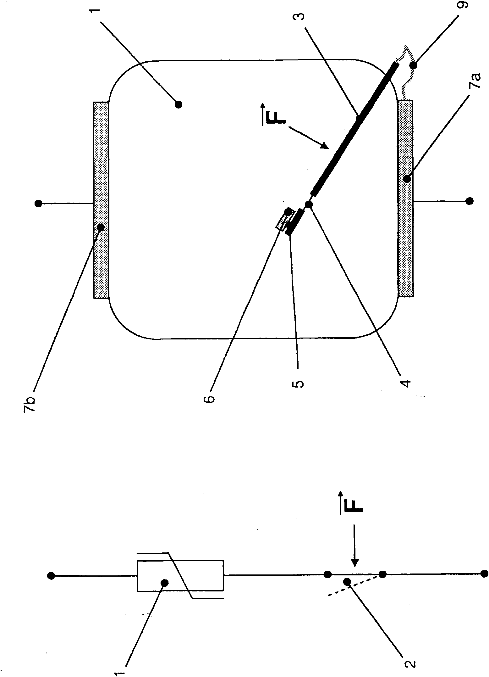
[0044] As already stated above, the object of the invention is to protect the varistor arrester and to ensure a targeted control of the disconnection behavior, especially in the event of a grid-frequency overvoltage.

[0045] figure 1 The known construction shown in consists of a varistor 1 with an integrated thermal separation 2 realized, for example, by a tongue under spring pretension. The tongue is secured to a contact by means of solder material, as per the figure 1 as shown in the figure on the right.

[0046] The solder material is designated here with the reference numeral 5 and the stationary contact with the reference numeral 6 . The tongue or movable contact arm 3 is connected to the piezoresistor connection 7a and is spring-forced to move it away from the opposing piezoresistor contact 6, so that a sufficiently large separation distance is created and the piezoresistor can be reliably connected to the piezoresistor. Grid separation. Usually, the varistor 1 cons...


PUM

PropertyMeasurementUnit
Thicknessaaaaaaaaaa

Abstract

The invention relates to a surge arrester comprising an integrated protection device, in particular against sustained, mains frequency overvoltage (TOV), comprising at least one varistor and a PTC resistor, which is in thermal contact with the varistor. The varistor and the PTC resistor are electrically connected in series. According to the invention, a ceramic disc with PTC resistor behaviour is situated between two varistor discs in a sandwich construction, said elements being directly interconnected both mechanically and electrically.

Description

technical field [0001] The invention relates to a surge arrester with integrated protective device according to the preamble of claim 1, in particular for continuous grid-frequency overvoltages (TOV), comprising at least one varistor and thermally connected to the varistor Contacting positive temperature coefficient thermistor (PTC resistor), wherein the piezoresistor and the PTC resistor are electrically connected in series. Background technique [0002] The combination of a series connection of an overvoltage protection element with a low freewheeling arc extinguishing capability, such as a spark gap or a gas discharge bleeder, with a positive temperature coefficient thermistor is known for voltage switches. Thus, DE 24 05 671 A1 shows such an application for direct current. When the protective element there responds, the positive temperature coefficient thermistor changes its resistance stepwise by the flowing freewheeling current (Folgestrom), and thus the current drops...

Claims


Application Information

Patent Timeline
IPC IPC(8): H01C7/12H02H3/08H02H9/04
CPCH01C7/126H02H9/042
Inventor A·厄尔哈德S·施雷特J·比奥赫拉维克D·格鲁兹曼W-R·莱茨施J·克雷茨施马尔
Owner DEHN SOHNE GMBH CO KG
Why Eureka
Try Eureka