Rotary testing device for vortex-induced vibration for oblique riser under shear current

A test device and vortex-induced vibration technology, applied in the field of marine engineering, can solve the problems of inability to simulate the vortex-induced vibration of a riser in a stepped flow field, difficult vortex-induced vibration testing, and small test distances, etc. Install, increase the effect of accuracy

Active Publication Date: 2011-05-11
SHANGHAI JIAO TONG UNIV
View PDF3 Cites 18 Cited by
  • Summary
  • Abstract
  • Description
  • Claims
  • Application Information

AI Technical Summary

Problems solved by technology

After analysis, the shortcomings of this test technology are: 1. Generally, it can only simulate the vortex-induced vibration of small-scale pipe fittings, and it is difficult to effectively carry out the vortex-induced vibration test under the real Reynolds number
2. Due to the limitation of the length of the deep water tank of the towed marine engineering, the distance of the test section obtained is relatively small, and the measured test data is less
3. Generally, only the vortex-induced vibration of the standpipe in the uniform flow field can be simulated, and the vortex-induced vibration of the standpipe in the stepped flow field cannot be simulated

Method used


Image

  • Rotary testing device for vortex-induced vibration for oblique riser under shear current
  • Rotary testing device for vortex-induced vibration for oblique riser under shear current
  • Rotary testing device for vortex-induced vibration for oblique riser under shear current

Examples


Embodiment 2

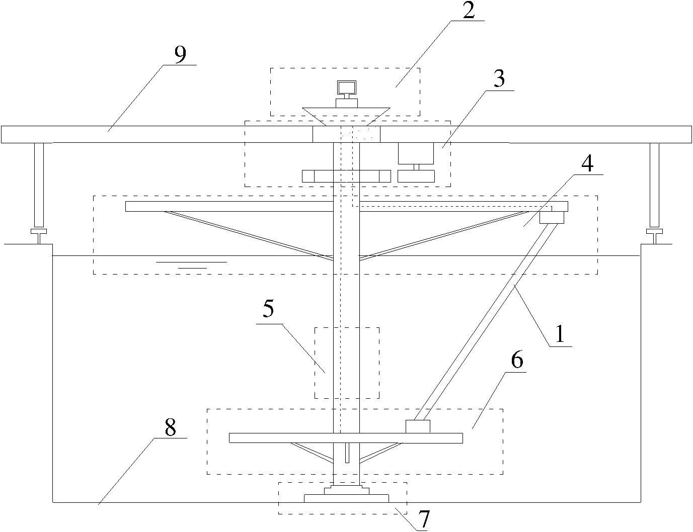
[0055] Such as Figure 1b As shown, the bottom riser fixing module 6 in this embodiment includes: a connecting flange 24, a bottom fixing cylinder shaft 25, a rectangular steel truss 44 and a rectangular support plate 45, wherein: one end of the rectangular support plate 45 is fixed to the bottom The cylindrical shaft 25 is connected, and the other end is connected with the lower end of the riser model 37. The upper part of the bottom fixed cylindrical shaft 25 is connected with the cylindrical shaft segment module 5 through the connecting flange 24, and the lower part is connected with the bottom supporting flange 26. Connected with the bottom support module 7, the connecting flange 24 is installed at the upper end of the bottom fixed cylindrical shaft 25 and connected with the cylindrical shaft segment module 5, and the rectangular steel truss 44 is installed at the lower position of the rectangular support plate 45 and connected to the bottom The fixed cylindrical shaft 25 ...

Embodiment 3

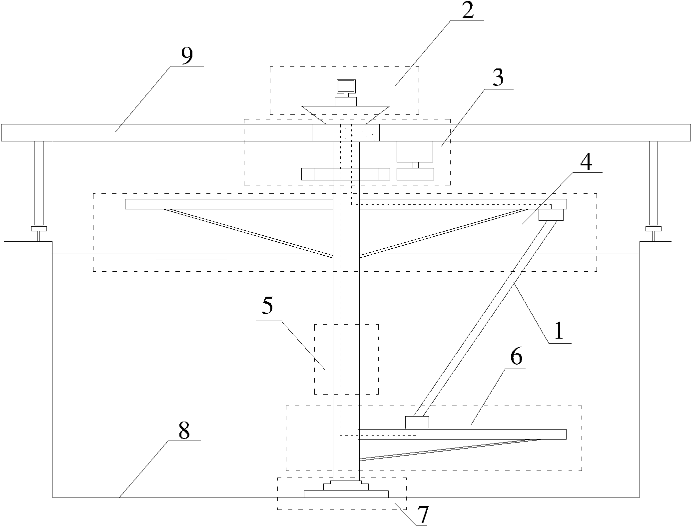
[0057] Such as Figure 1c As shown, the bottom riser fixing module 6 in this embodiment includes: a connecting flange 24, a bottom fixing cylinder shaft 25, a bottom fixing end 46 of the riser, an opening 47 on the bottom fixing cylinder shaft, a bottom fixing cylinder shaft The lower opening 48, wherein the upper part of the bottom fixed cylindrical shaft 25 is connected to the cylindrical shaft segment module 5 through the connecting flange 24, and the lower part is connected to the bottom supporting module 7 through the bottom supporting flange 26. The riser model 37 is fixed inside the bottom fixed cylinder shaft 25 through the bottom fixed end 46 of the riser through the upper opening 47 of the bottom fixed cylinder shaft and the lower opening 48 of the bottom fixed cylinder shaft.


PUM


Abstract

The invention relates to a rotary testing device for vortex-induced vibration for an oblique riser under shear current, belonging to the technical field of ocean engineering. The rotary testing device comprises a riser model mechanism, a measurement and analysis system platform module, a driving module, a top cantilever module, a cylinder shaft segmentation module, a bottom riser fixing module and a bottom supporting module, wherein the riser model mechanism is fixedly arranged between the top cantilever module and the bottom riser fixing module; the cylinder shaft segmentation module is vertically arranged in an ocean engineering deepwater basin and respectively connected with the bottom supporting module, the driving module, the top cantilever module and the bottom riser fixing module; the bottom supporting module is fixedly arranged on a lifting bottom; the driving module is connected with the cylinder shaft segmentation module and outputs power; both ends of the top cantilever module are connected with the driving module or the cylinder shaft segmentation module and the cylinder shaft segmentation module; and the measurement and analysis system platform module is connected with the riser model mechanism, the top cantilever module and the bottom riser fixing module. The invention can simulate risers of actual sizes and shear current fields.

Description

technical field [0001] The invention relates to a device in the technical field of marine engineering, in particular to a vortex-induced vibration rotating test device for a flexible riser model placed obliquely in a deep pool of marine engineering under shear flow. Background technique [0002] According to fluid mechanics, when a columnar structure is placed in the incoming flow at a certain speed, vortices will alternately shed on both sides. Associated with the creation and discharge of vortices, the column is subjected to lateral and flow-wise pulsating pressures. If the column is elastically supported at this point, the pulsating fluid forces will induce vibrations in the column, which in turn will change the structure of its wake. This fluid-structure interaction problem is called vortex-induced vibration. For example, under the action of ocean currents, vortex-induced vibrations will occur on flexible pipes such as offshore platform risers, tow cables, submarine pi...

Claims


Application Information

Patent Timeline
Patent Type & Authority Applications(China)
IPC IPC(8): G01M7/02
Inventor 付世晓杨建民任铁李润培
Owner SHANGHAI JIAO TONG UNIV
Why Eureka
Try Eureka