Method for steering a mining machine cutter

A mining machine, machine technology, applied in the field of manipulating mining machine cutters, can solve problems such as machine damage

Inactive Publication Date: 2011-05-18
JOY GLOBAL UNDERGROUND MINING LLC
View PDF7 Cites 24 Cited by
  • Summary
  • Abstract
  • Description
  • Claims
  • Application Information

AI Technical Summary

Problems solved by technology

If this problem occurs, the rocker arm is below the undercut limit and the cutting machine can cut into the bottom of the dig, causing possible damage to the machine

Method used


Image

  • Method for steering a mining machine cutter
  • Method for steering a mining machine cutter
  • Method for steering a mining machine cutter

Examples


Embodiment Construction

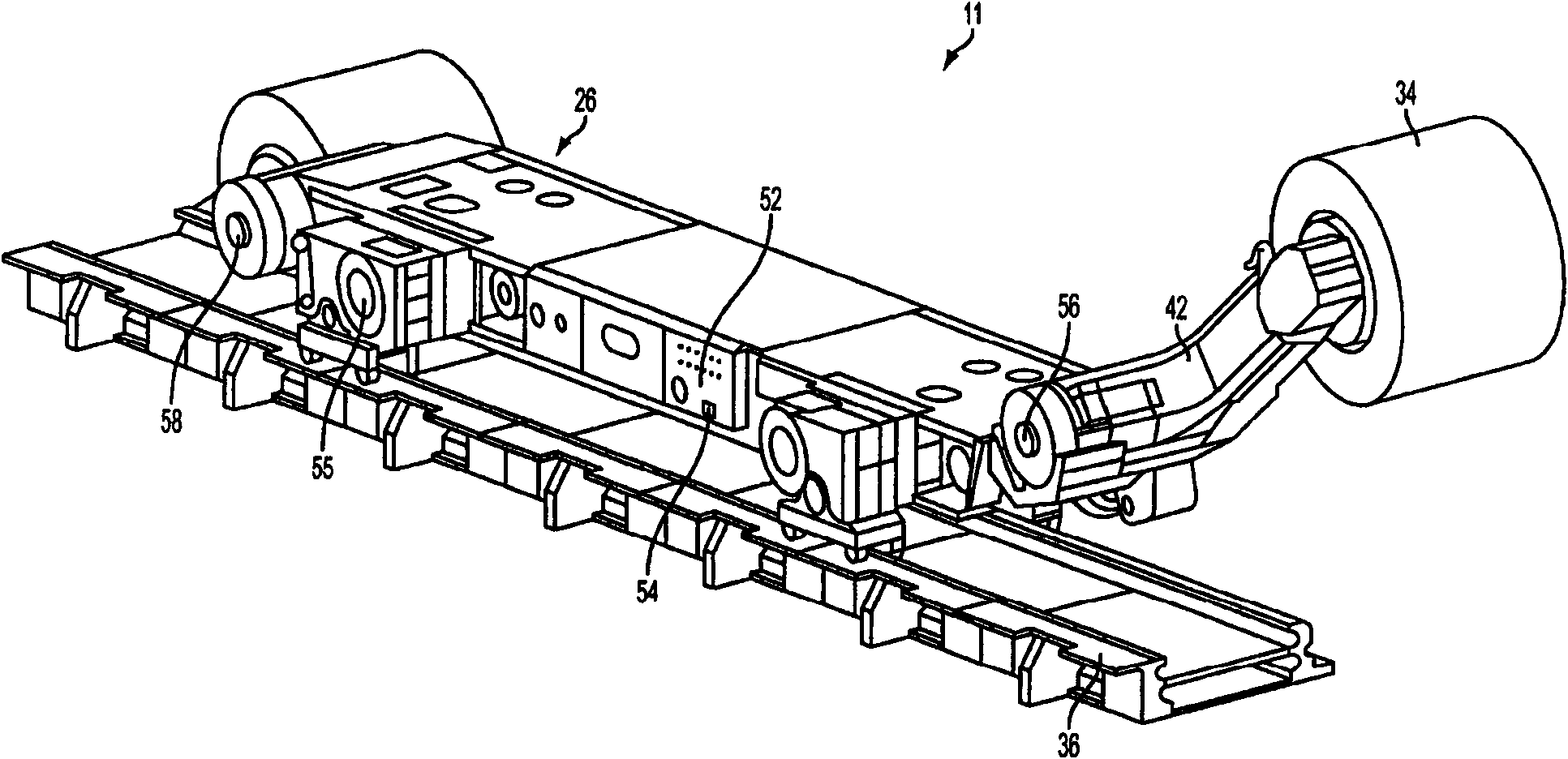
[0021] exist figure 1 One type of mining equipment 11 is illustrated in , which includes a mobile mining or cutting machine in the form of a cutter 26 having a rotatable cutting or mining head 34 which A plurality of cutting bits 38 are provided and are used to remove media from layers (not shown). The cutting head 34 is attached to a moving boom arrangement 42 which enables the position of the cutting head 34 to be adjusted relative to the mining floor. As cutting head 34 rotates and advances into the seam, coal is removed from the mining workers and received on collecting and conveying equipment 36 of coal mining equipment 11 . Conveyor 36 discharges mined material onto a separate stand-alone conveyor or mobile conveyor (not shown) for eventual conveyance out of the mine. The front cutting head 34 cuts the top part of the layer and the rear cutting head extracts the remaining part. The cutting machine is dragged along armored conveyors in the conventional manner as it cut...


PUM


Abstract

The invention relates to a method for steering a mining machine cutter. A control system monitors the angle of each ranging arm, with respect to the mainframe of the machine. While the machine is in a defined zone along the face, if the angle of the arm is detected to be lower than a parameter defined set-point called the undercut limit, the control system does not allow the arm to be lowered further. When entering the run of face from either gate end, if either of the ranging arms are below the set point, the horizontal movement of the shearer is stopped, and an alarm message is generated, and a warning light begins to flash, alerting the operator that he must raise the arm before horizontal movement of the shearer can be enabled.

Description

technical field [0001] The present invention relates to a method for manipulating a mining machine cutter, wherein said mining machine is of the kind having a body arranged to advance along the face of a miner being cut, the body having at either end Ranging arms are rotatably mounted on the main body and each arm carries a rotatable cutting drum. Such a machine is known as a double-ended ranging roller shearer. Background technique [0002] Many devices are known for cutting and extracting the desired mineral, but one common form used in particular for coal mining is the use of range-drum machines with rocker arms at either end, wherein the At the end of each rocker arm of the main body of the machine, a cutting drum with a plurality of cutting teeth is rotatable. The main body of the machine moves along the work zone, and each rotating drum cuts material from the work zone. [0003] This type of machine is rigged to keep the drum cutting within the seam by adjusting the...

Claims


Application Information

Patent Timeline
Patent Type & Authority Applications(China)
IPC IPC(8): E21C25/10E21C31/02
CPCE21C35/24E21C27/02
Inventor 爱德华·F·尼德赖特格里高利·S·威尔森
Owner JOY GLOBAL UNDERGROUND MINING LLC
Why Eureka
Try Eureka