
Heat radiation structure and projector thereof

A technology of heat dissipation structure and projector, applied in cooling/ventilation/heating transformation, optics, instruments, etc., can solve problems such as increasing manufacturing cost, controlling design complexity, and easy overheating and damage of electronic components.

Inactive Publication Date: 2011-05-25
QISDA OPTRONICS (SUZHOU) CO LTD +1
View PDF5 Cites 6 Cited by
  • Summary
  • Abstract
  • Description
  • Claims
  • Application Information

AI Technical Summary

Problems solved by technology

However, in the case of independent flow channels, if one of the flow channels cannot perform heat dissipation due to blockage and there is no detection device in this flow channel to activate the protection mechanism, the electronic components in this flow channel are easily overheated and damaged
If temperature sensing elements are installed in each independent flow channel, the above-mentioned problems of overheating and damage to electronic components due to blockage can be avoided, but it will also increase the manufacturing cost and the complexity of control design

Method used


Image

  • Heat radiation structure and projector thereof
  • Heat radiation structure and projector thereof
  • Heat radiation structure and projector thereof

Examples


Embodiment Construction

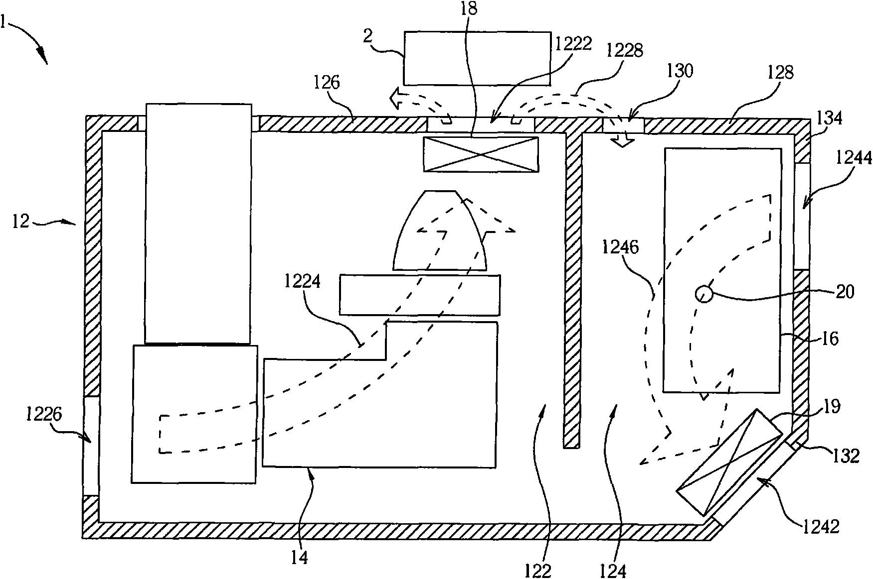
[0019] see figure 1 , which is a schematic diagram of the projector 1 according to the first embodiment of the present invention. The projector 1 includes a casing 12 , an optical engine 14 (optical engine), and a lamp 16 . The casing 12 has substantially independent first heat dissipation space 122 and second heat dissipation space 124 therein. The casing 12 includes a first side wall 126 and a second side wall 128 adjacent to the first side wall 126. The first air outlet 1222 forms The through hole 130 is formed on the second side wall 128 adjacent to the first air outlet 1222 and communicates with the second heat dissipation space 124 on the first side wall 126 and communicates with the first heat dissipation space 122 . The first heat dissipation airflow 1224 (indicated by a dotted hollow arrow) can flow through the first heat dissipation space 122 and flow out of the housing 12 from the first airflow outlet 1222 .

[0020] In practice, the casing 12 usually has a first ...


PUM


Abstract

The invention provides a heat radiation structure and a projector with the heat radiation structure. The heat radiation structure comprises a housing, wherein a first heat radiation space and a second heat radiation space are arranged in the housing, the housing comprises a first side wall and a second side wall which is near to the first side wall, an airflow outlet is formed on the first side wall and communicated with the first heat radiation space, a through hole is formed on the second side wall which is near to the airflow outlet and communicated with the second heat radiation space, and heat radiation airflow can circulate in the first heat radiation space and flow out of the housing from the airflow outlet. When the airflow outlet is blocked, at least one part of the heat radiation air flow penetrates the through hole and flow into the second heat radiation space. Therefore, an electronic element arranged in the first heat radiation space can not be damaged due to overheating when the effectiveness of a heat radiation system is greatly reduced or fails.

Description

【Technical field】 [0001] The invention relates to a heat dissipation structure of an electronic device and a projector with the heat dissipation structure, in particular to the heat dissipation structure and the projector which prevent electronic components in the heat dissipation space from overheating by designing a flow path. 【Background technique】 [0002] At present, daily life is full of various electronic devices, and electronic devices always have heat dissipation problems. When the heat dissipation is insufficient and the operating characteristics of electronic components are affected, not only the life of electronic components will be shortened, but the operation stability of the entire electronic device will also be affected. Will be affected, or even fail. Taking a projector as an example, in addition to the light bulb as the main heat source, a lamp ballast for providing a stable voltage to the light bulb also generates considerable heat during operation. In ad...

Claims


Application Information

Patent Timeline
Patent Type & Authority Applications(China)
IPC IPC(8): G03B21/16H05K7/20
Inventor 施建宇
Owner QISDA OPTRONICS (SUZHOU) CO LTD
Learn More