Alternative current generator system for vehicle
An alternating current, generator technology, applied in synchronous motors with stationary armatures and rotating magnets, electrical components, electromechanical devices, etc., to solve problems such as waste, short circuit regulator circuits, and reduced operating efficiency of alternating current generators
- Summary
- Abstract
- Description
- Claims
- Application Information
AI Technical Summary
Problems solved by technology
Method used
Image

Examples
no. 1 example
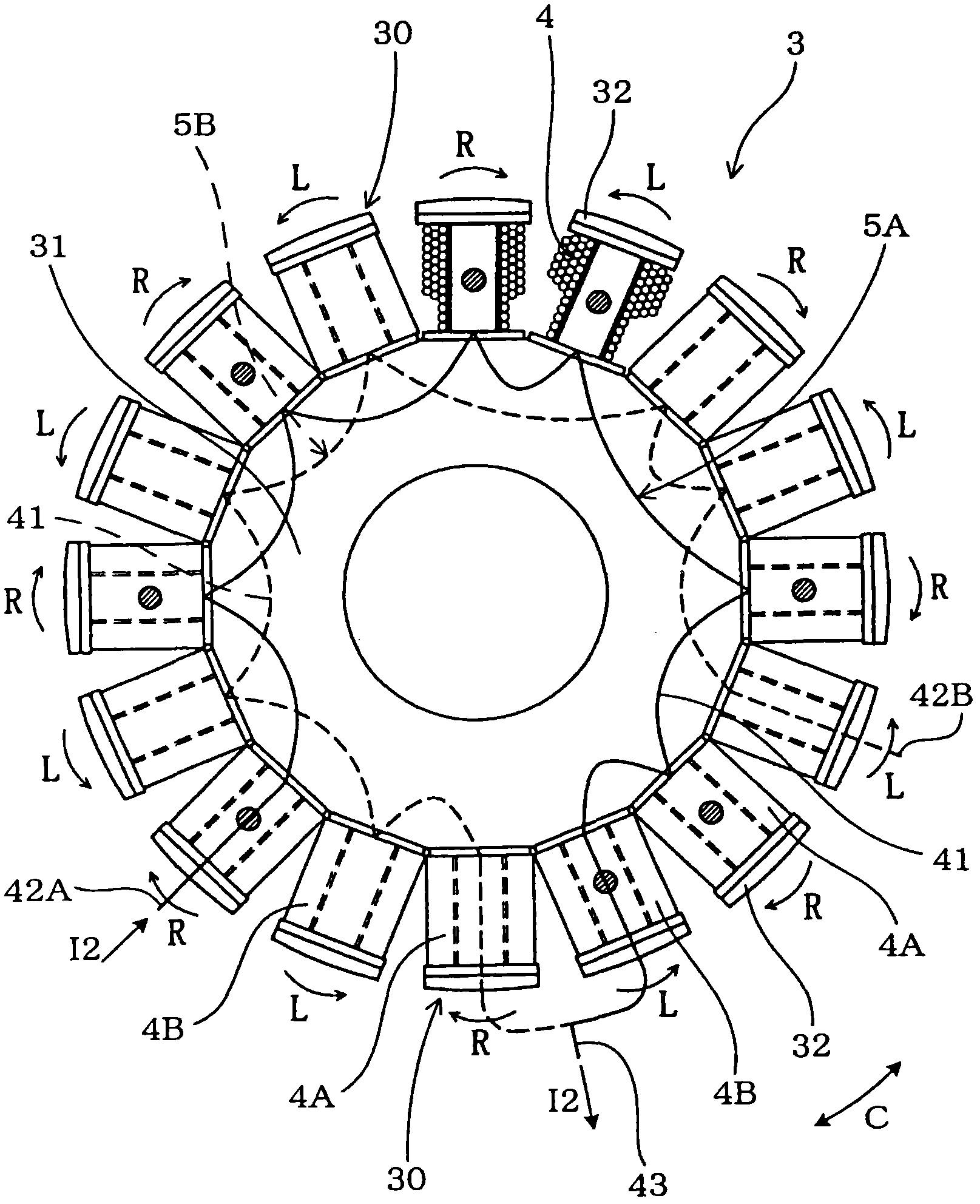
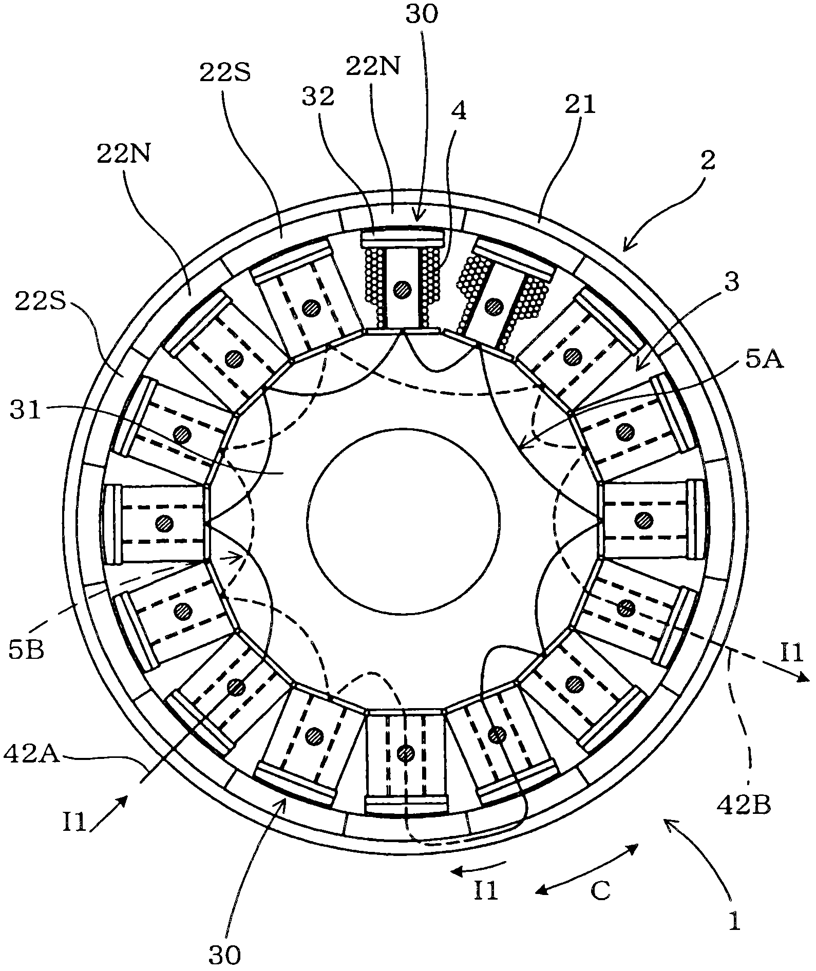
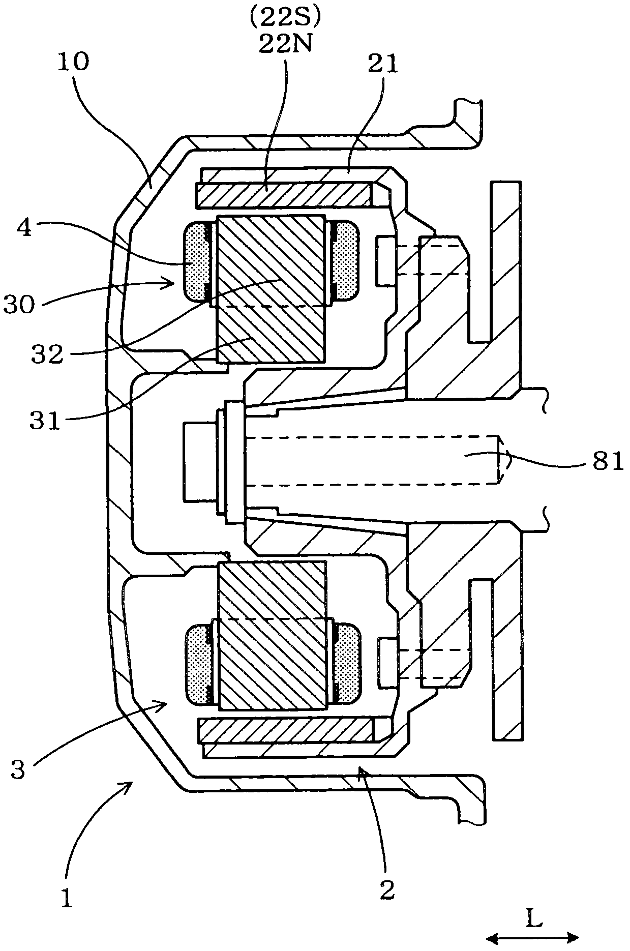
[0028] see figure 1 , 2 and 3, the alternator 1 has an outer rotor 2 and a stator 3. The outer rotor 2 has a plurality of permanent magnets 22 (22N and 22S) arranged in the circumferential direction C such that N-pole magnetic field generating portions 22N and S-pole magnetic field generating portions 22S of the permanent magnets alternate with each other. The stator 3 is located radially inward of the outer rotor 2 and has a central core portion 31 on which a plurality of magnetic poles 30 protruding in a radially outward direction are arranged in the circumferential direction C. Each pole 30 has a pole core portion 32 and a coil 4 which is part of a coil group and is referred to as a winding portion. The coil 4 is wound around the pole 30 in opposite directions between right-handed and left-handed with respect to the pole core portion 32 so that the direction of the winding becomes opposite to the direction of the winding of the adjacent pole 30 . Since the N-pole magneti...
no. 2 example
[0067] According to the second embodiment, switching between the full generating operation state W1 of the alternator 1 and the partial generating operating state W2 is performed in another scheme than that of the first embodiment.
[0068] Such as Figure 14 As shown in , the predetermined acceleration time transition speed A for shifting from the full power generation operation state W1 to the partial power generation operation state W2 is set within the pre-engagement speed range R1 between the disengagement speed N1 and the engagement start speed N2. The predetermined deceleration-time switching rotational speed B for transitioning from the part-generating operation state W2 to the full-generating operation state W1 is set lower than the predetermined acceleration-time switching rotational speed A in the pre-coupling rotational speed range R1. Alternatively, the rotation speed B may be set slightly lower than the disengagement rotation speed N1. The second embodiment is a...
PUM
 Abstract
Description
Claims
Application Information
 - R&D
- Intellectual Property
- Life Sciences
- Materials
- Tech Scout
- Unparalleled Data Quality
- Higher Quality Content
- 60% Fewer Hallucinations
Browse by: Latest US Patents, China's latest patents, Technical Efficacy Thesaurus, Application Domain, Technology Topic, Popular Technical Reports.
© 2025 PatSnap. All rights reserved.Legal|Privacy policy|Modern Slavery Act Transparency Statement|Sitemap|About US| Contact US: help@patsnap.com