
Computer panel key device

A computer panel and button technology, applied in the direction of digital processing power distribution, instruments, record carrier structural parts, etc., can solve problems such as inconvenient operation, and achieve the effect of reducing the operation stroke

Inactive Publication Date: 2011-06-01
HONG FU JIN PRECISION IND WUHAN CO LTD +1
View PDF6 Cites 2 Cited by
  • Summary
  • Abstract
  • Description
  • Claims
  • Application Information

AI Technical Summary

Problems solved by technology

Usually, the key abuts against one end of the pivoting member, and the optical drive button corresponds to the middle position of the pivoting member. When the pivoting member is pushed by the key, it pivots around the other opposite end to press the optical drive button. In this way, the operating stroke of the button is generally greater than the actual stroke of the optical drive button when the optical drive tray is opened, resulting in inconvenient operation

Method used


Image

  • Computer panel key device
  • Computer panel key device
  • Computer panel key device

Examples


Embodiment Construction

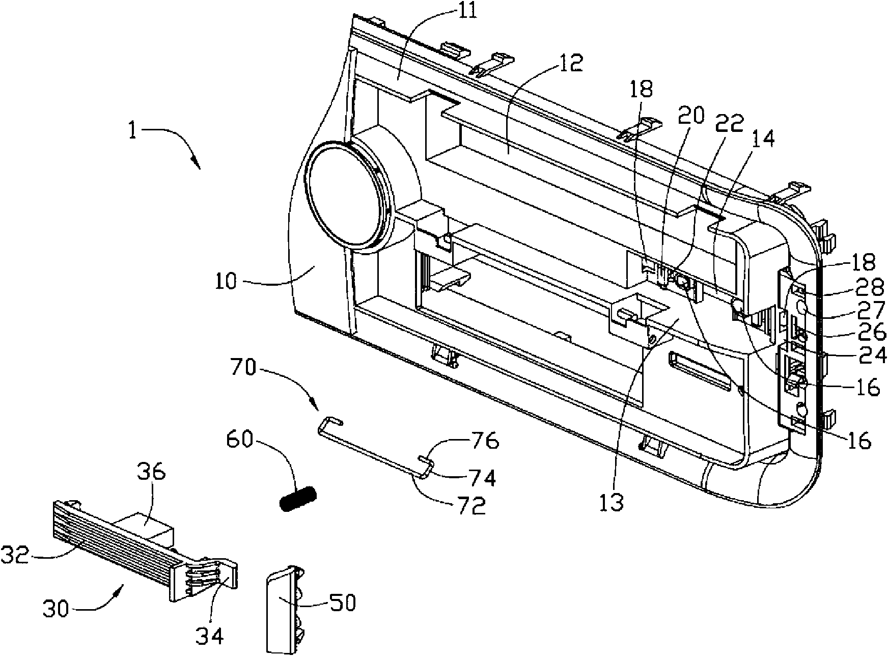
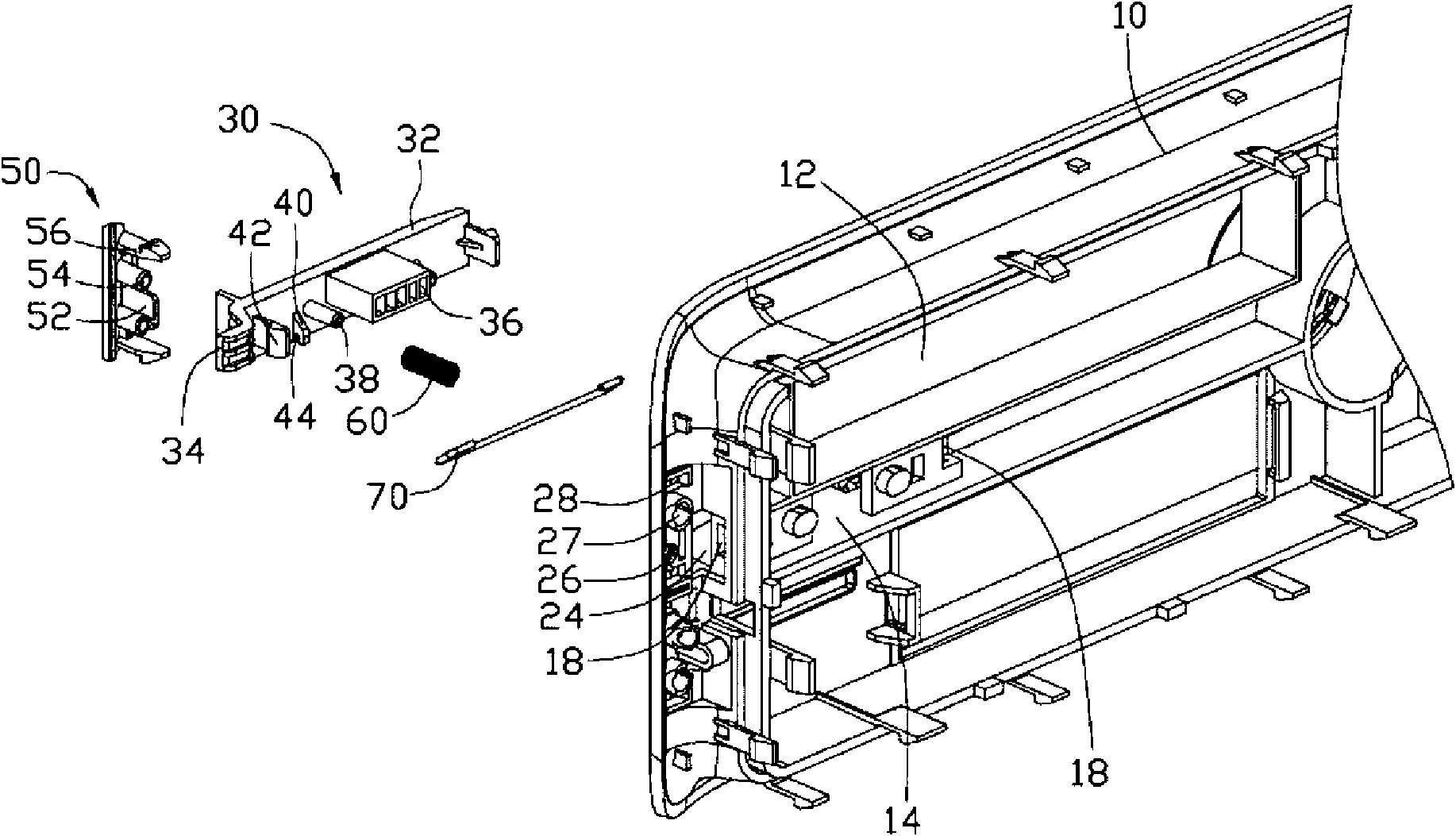
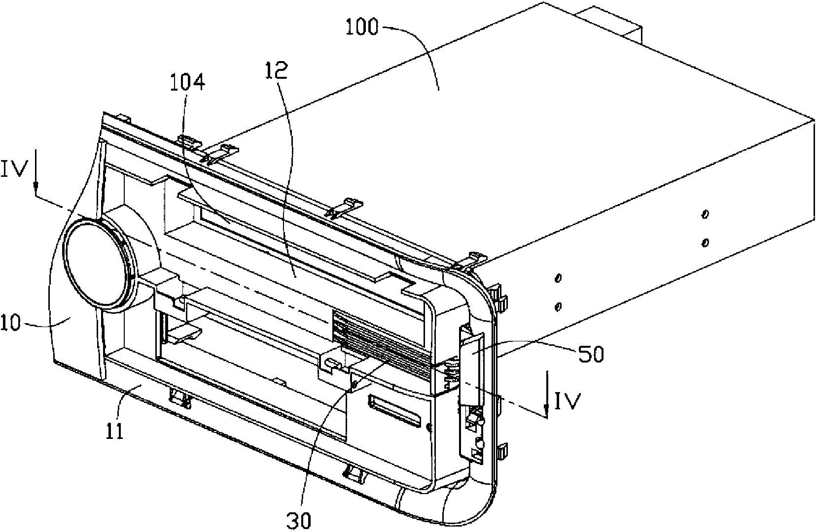
[0015] Please refer to Figure 1 to Figure 4 A preferred embodiment of the computer panel key device 1 of the present invention can be installed in a computer case (not shown) equipped with an optical drive 100 to press the button 102 of the optical drive 100 that is arranged hidden. The preferred embodiment of the computer panel key device 1 includes a panel 10, a pressing member 30, a button 50, an elastic member for resetting the pressing member 30, and a linkage member 70 for allowing the pressing member 30 to perform translational movement. In this embodiment, the elastic member is a spiral compression spring 60.

[0016] The panel 10 is provided with an optical drive installation area 11, the installation area 11 defines an exit 12 through which the tray 104 of the optical drive 100 extends, and an embedded groove 13 is opened at the lower right of the exit 12. A through hole 14 is defined on the rear side of the embedding groove 13. Two accommodating holes 16 and two cla...


PUM


Abstract

The invention relates to a computer panel key device, comprising a panel, a pressing piece, an elastic piece and a linkage piece. The pressing piece is mounted on the panel to trigger a CD driver button; the elastic piece is used for resetting the pressing piece, and the linkage piece is arranged between the pressing piece and the panel so that the pressing piece can make translational motion relative to the panel. When the computer panel key device is mounted on a computer case with a CD driver, the pressing piece faces to the CD driver button; when the pressing piece is pressed, the pressing piece is driven by the linkage piece to make translational motion relative to the panel and trigger the CD driver button to reduce the operation process of the pressing piece; and the design of the pressing piece is matched with the appearance of the panel to reach the effect of attractive appearance.

Description

Technical field [0001] The invention relates to a computer panel key device. Background technique [0002] In order to meet the different needs of users for computer case panels, the appearance design of computer case panels has been diversified. In this way, when the front panel with buttons on the optical drive is embedded in the opening on the computer case panel so that the buttons on the front panel are exposed on the computer case panel, the design of the front panel of the optical drive and the computer case panel often appear The unmatched appearance design affects the appearance of the computer case panel. At this time, a hidden optical drive appeared, and the button of the optical drive hidden behind the computer case panel was pressed through the button device installed on the computer case panel. [0003] Currently, this type of key device includes keys that are exposedly installed on the panel of the computer case and a pivoting member for pressing the buttons of the...

Claims


Application Information

Patent Timeline
Patent Type & Authority Applications(China)
IPC IPC(8): H01H3/12G06F1/18G11B17/02G11B33/00
Inventor 耿运栋
Owner HONG FU JIN PRECISION IND WUHAN CO LTD
Learn More