
Method and device for realizing unbalanced load sharing

A load sharing and unbalanced technology, applied in the direction of digital transmission system, electrical components, transmission system, etc., can solve the problems of increasing the amount of IGP calculation, difficult implementation, and large IP address resources occupied by tunnel ports, so as to save IP address resources, The effect of saving IGP protocol resources

Inactive Publication Date: 2011-06-01
NEW H3C TECH CO LTD
View PDF4 Cites 6 Cited by
  • Summary
  • Abstract
  • Description
  • Claims
  • Application Information

AI Technical Summary

Problems solved by technology

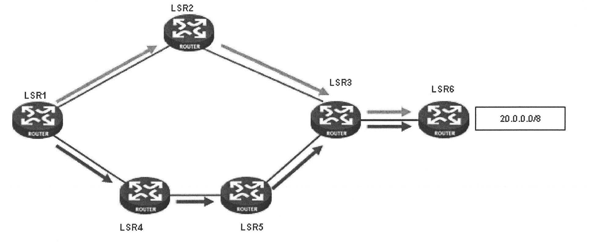
[0007] 2. Such as figure 1 If the IGP ShortCut function is enabled at the headend of the LSR1 tunnel shown in , each tunnel port must be configured with an IP address and IGP enabled, so that the tunnel port will occupy a large amount of IP address resources and increase the calculation of IGP. quantity
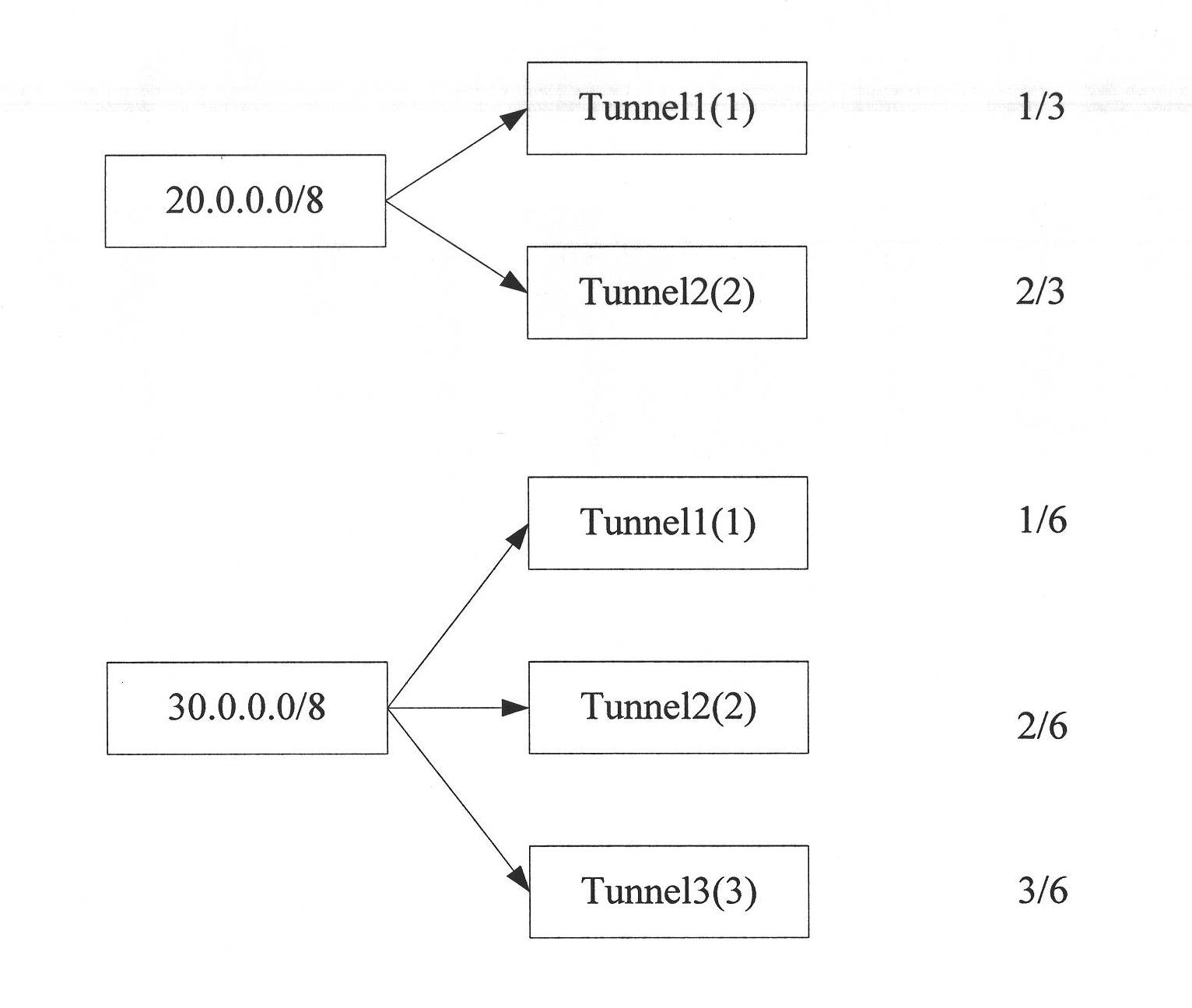
Suppose there are two routes 20.0.0.0 / 8 and 30.0.0.0 / 8, and the route 20.0.0.0 / 8 has two tunnels Tunnel1 and Tunnel2 as the equal-cost forwarding path, you need to maintain the load sharing factor 1 of Tunnel1 and Tunnel2 of this route The load sharing factor of Tunnel1 and Tunnel2 must be maintained at 2, and the route 30.0.0.0 / 8 has three tunnels as equal-cost forwarding paths, so it is necessary to maintain the load sharing factor of Tunnel1 at 1, the load sharing factor of Tunnel2 at 2, and the load of Tunnel3 The sharing factor is 3, and the status of Tunnel1, Tunnel2 and Tunnel3 must be maintained. figure 2 Shown is just a simple case, for scenarios with a large number of routes, it is very difficult to implement

Method used


Image

  • Method and device for realizing unbalanced load sharing
  • Method and device for realizing unbalanced load sharing
  • Method and device for realizing unbalanced load sharing

Examples


Embodiment Construction

[0029] In order to make the objects and advantages of the present invention clearer, the present invention will be further described in detail below in conjunction with the accompanying drawings and embodiments.

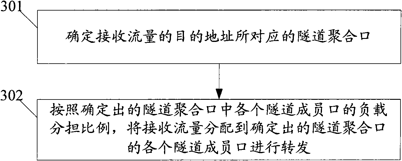
[0030] In the present invention, the tunnel ports corresponding to the same destination address are added in advance to the tunnel aggregation port corresponding to the same destination address as the tunnel member ports of the tunnel aggregation port, and the load sharing ratio of each tunnel member port in each tunnel aggregation port is configured.

[0031] The tunnel aggregation port among the present invention is the logical port of the network layer, has all the functions of the common tunnel port in the prior art, for example can configure IP address, enable IGP, configure multi-protocol label switching (MPLS, Multi-Protocol Label Switch) and Routing protocols, etc., can also participate in the VPN feature selection of public network tunnels, and each tunnel me...


PUM


Abstract

The invention discloses a method and device for realizing unbalanced load sharing, which is realized by transferring the functions of multiple common tunnel entrances corresponding to the same destination address to a tunnel converging entrance with the same destination address, thus the common tunnel entrances only execute the transmitting function, so that firstly, equivalence on a route term does not need to be carried out on the multiple tunnel entrances and then unbalanced load sharing is carried out aiming at each tunnel entrance after the equivalence, but unbalanced load sharing needs to be carried out only on the tunnel converging entrance; secondly, no matter how many routes are transmitted through the tunnel converging entrance corresponding to the destination address, the load sharing ratio of the tunnel converging entrance is unchangeable; thirdly, the tunnel entrances do not need to allocate the IP (Internet Protocol) address or enable an IGP (Interior Gateway Protocol), thereby greatly saving IP address resources and IGP resources; and fourthly, only the load sharing ratio of the tunnel converging entrance needs to be maintained, but the load sharing ratio does not need to be maintained aiming at each route.

Description

technical field [0001] The invention relates to load sharing technology, in particular to a method and device for realizing unbalanced load sharing. Background technique [0002] Tunnel transmission is a way of data transmission, using the tunneling protocol to re-encapsulate data frames or data packets of other protocols, and then send them through the tunnel. Multiple tunnels can be established between two network devices to achieve load sharing of data transmission. When the established multiple tunnels have different reserved bandwidths, there is a requirement for unbalanced load sharing. The following uses traffic engineering (TE , Traffic Engineering) tunnel as an example, briefly describe the application of this unbalanced load sharing. [0003] As the main technology of TE, TE tunnel is widely used in common Internet Protocol (IP, Internet Protocol) forwarding, Layer 2 Virtual Private Network (L2VPN, Layer 2 Virtual Private Network), and Layer 3 Virtual Private Netw...

Claims


Application Information

Patent Timeline
IPC IPC(8): H04L12/56H04L29/08H04L12/803
Inventor 郜忠华
Owner NEW H3C TECH CO LTD
Learn More