Prestressing cradle frame of electrolysis bath

A cradle frame and electrolytic cell technology, applied in the field of aluminum electrolytic cells, can solve problems such as large deformation

Active Publication Date: 2013-05-15
GUIYANG AL-MG DESIGN & RES INST
View PDF4 Cites 0 Cited by
  • Summary
  • Abstract
  • Description
  • Claims
  • Application Information

AI Technical Summary

Problems solved by technology

[0005] The technical problem to be solved by the present invention is to provide a prestressed electrolytic cell cradle, which has a simple structure and reliable operation, can improve the internal force performance of the cradle and the electrolytic cell, and at the same time greatly reduce the cost of the electrolytic cell. To overcome the large deformation of the cantilever end of the cradle frame of the electrolytic cell caused by the expansion of the tank shell in the prior art, a large shear force and bending moment are generated at the end of the cradle frame, and shearing and pulling cracks occur at the root of the cradle frame. insufficient

Method used


Image

  • Prestressing cradle frame of electrolysis bath
  • Prestressing cradle frame of electrolysis bath
  • Prestressing cradle frame of electrolysis bath

Examples


Embodiment Construction

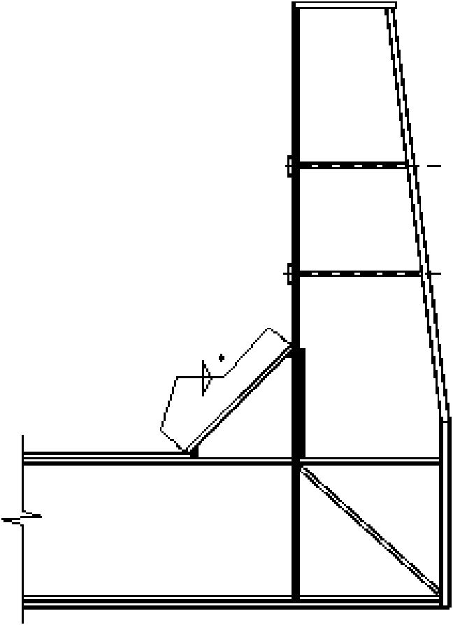
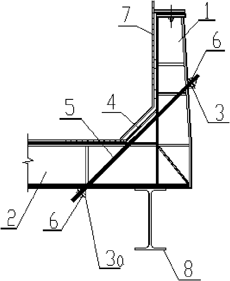
[0015] Embodiments of the invention: as figure 2 As shown, it includes the cantilever end 1 of the cradle frame, the bottom beam 2 of the cradle frame, the electrolytic tank shell 7, the AB beam 8 of the electrolytic cell, the upper end of the prestressed tension rod 5 is connected with the cantilever end 1 of the cradle frame, and the lower end is connected with the bottom of the cradle frame Girder 2 connection.

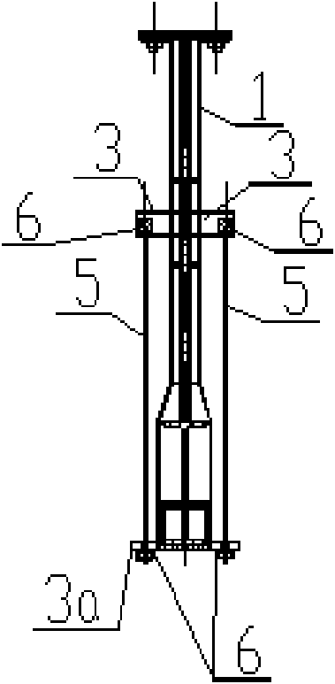
[0016] The number of prestressed tie rods 5 is two, which are respectively connected to both sides of the cantilever end 1 of the cradle frame and the bottom beam 2 of the cradle frame. From figure 2 Look, the two prestressed tie rods 5 are located at the front and rear sides of the cantilever end 1 of the cradle frame and the bottom beam 2 of the cradle frame. image 3 See, 2 prestressed pull rods 5 are located at the left and right sides of the cantilever end 1 of the cradle frame and the bottom beam 2 of the cradle frame.

[0017] On the cantilever end 1 of...


PUM


Abstract

The invention discloses a prestressing cradle frame of an electrolysis bath, which comprises an electrolysis bath shell (7) and an electrolysis bath AB beam (8), wherein the upper end of a prestressed pull rod (5) is connected with a cantilever end (1) of the cradle frame, and the lower end of the prestressed pull rod is connected with a bottom girder (2) of the cradle frame. An upper fulcrum (3)of the prestressed pull rod is arranged at the cantilever end (1) of the cradle frame; a lower fulcrum (3a) of the prestressed pull rod is arranged on the bottom girder (2) of the cradle frame; the prestressed pull rod (5) is connected with the cantilever end (1) of the cradle frame through the upper fulcrum (3) of the prestressed pull rod, and connected with the bottom girder (2) of the cradle frame through the lower fulcrum (3a) of the prestressed pull rod. An anchoring end (6) is arranged at the upper end and lower end of the prestressed pull rod (5). The upper section of a stiffening plate (4) is arranged between the cantilever end (1) of the cradle frame and the electrolysis bath shell (7), and the lower section is arranged at the intersection of the cantilever end (1) of the cradle frame and the bottom girder (2) of the cradle frame and positioned on the prestressed pull rod (5).

Description

technical field [0001] The invention relates to a cradle frame structure for an electrolytic cell, belonging to the technical field of aluminum electrolytic cells. Background technique [0002] The cradle frame is the key component of electrolytic aluminum production. Modern large-scale aluminum electrolytic cells mostly use cradle-type shells, and the lower structure is mainly composed of electrolytic cell shells and a series of cradle frames. The long side load of the tank shell is mainly borne by the cradle frame. In the actual use process, it is found that the deformation of the long side of the tank shell is the main factor affecting the working capacity of the tank shell. The main reason for the deformation of the electrolytic cell is that as the electrolytic cell starts to operate, the temperature of the large surface end of the cell rises, and the expansion stress absorbed by the inner liner, the welding internal stress and the thermal stress cause the expansion of ...

Claims


Application Information

Patent Timeline
IPC IPC(8): C25C3/10
Inventor 郑莆余祥兴孙建
Owner GUIYANG AL-MG DESIGN & RES INST
Why Eureka
Try Eureka