Humidifying device

A humidification device and component technology, applied in air humidification systems, heating methods, lighting and heating equipment, etc., can solve the problems of increased water injection volume, complicated control, and inability to automatically change the water volume of the humidification drum, and achieve simple control Effect

Active Publication Date: 2011-06-08
DAIKIN IND LTD
View PDF9 Cites 3 Cited by
  • Summary
  • Abstract
  • Description
  • Claims
  • Application Information

AI Technical Summary

Problems solved by technology

[0004] However, in the conventional humidifier described above, even if the rotation speed of the fan is changed to change the blowing air volume, the amount of water injected into the humidifying drum cannot be automatically changed.
Therefore, conventionally, there has been a problem that the rotation speed of the vaporization filter increases in response to the increase in the rotation speed of the fan, and the amount of water injected from the bailer must also be increased, complicating the control.

Method used


Image

  • Humidifying device
  • Humidifying device
  • Humidifying device

Examples


Embodiment Construction

[0064] Hereinafter, the present invention will be described in detail based on the illustrated embodiments.

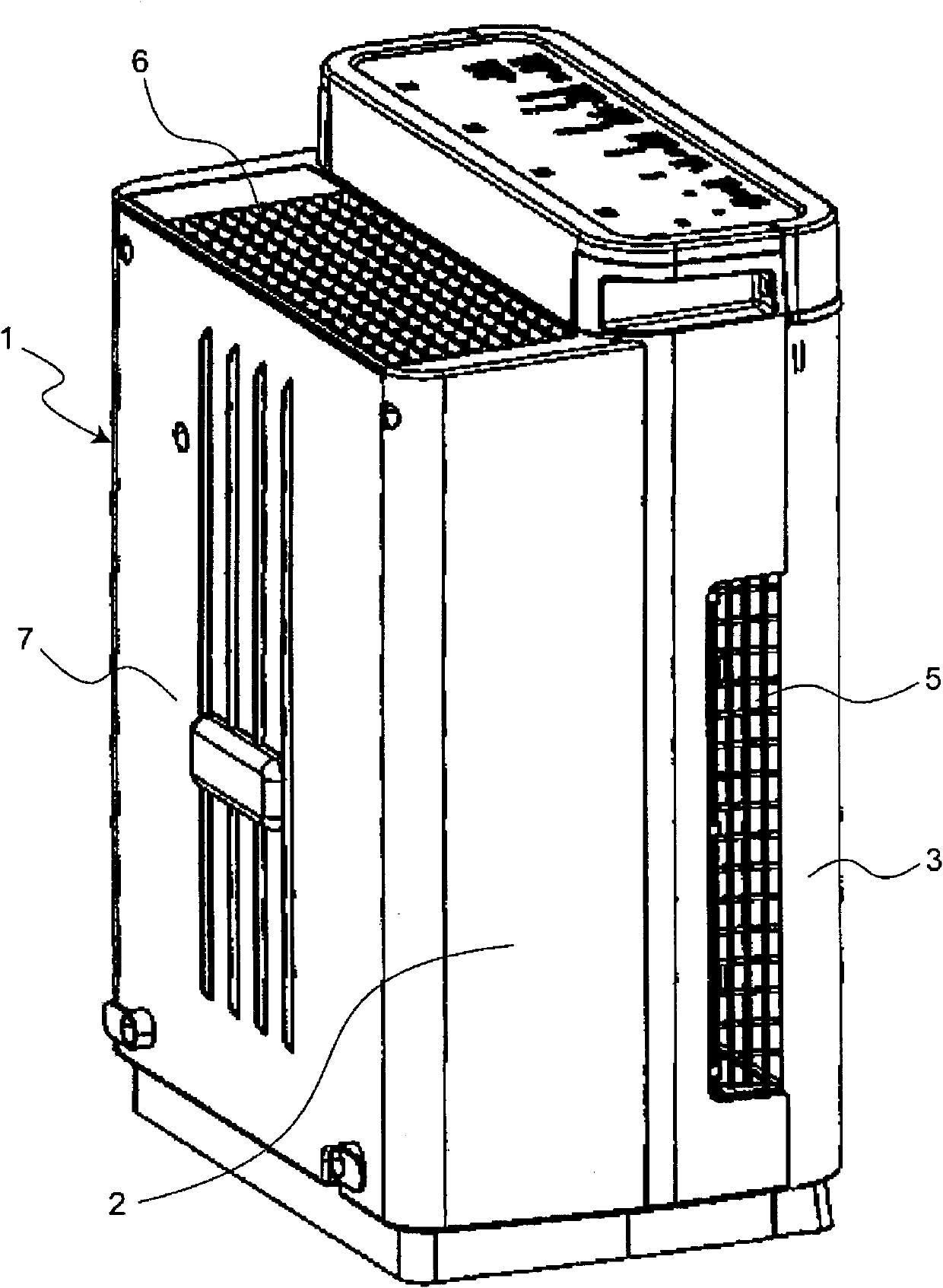
[0065] Such as figure 1 As shown, the humidifier includes a housing 1, which is composed of a housing main body 2 and a front panel 3 detachably mounted on the housing main body 2.

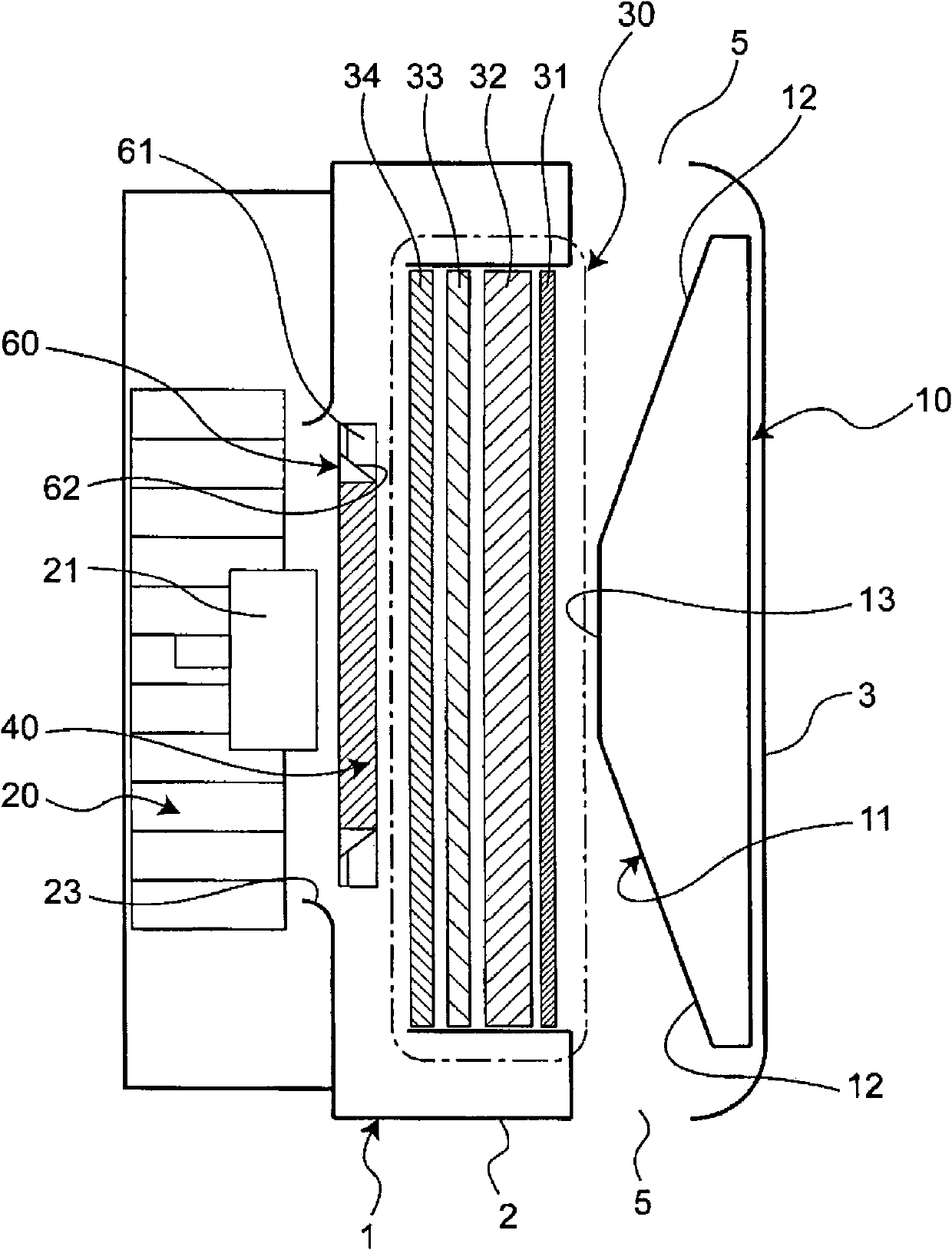
[0066] Suction ports 5, 5 are provided on both sides of the housing 1 (refer to image 3 ), an air outlet 6 is provided at the rear portion of the upper surface of the casing 1.

[0067] In this way, in this humidifier, the suction ports 5 and 5 are provided on the side surfaces of the casing 1, the blowing outlet 6 is provided on the upper surface of the casing 1, and the rear surface 7 of the casing 1 does not have the suction port and the blowing port. Therefore, the rear surface 7 of the casing 1 of the humidifier can be in close contact with the wall surface of the room (not shown), and the degree of freedom of installation of the humidifier is high.

[0068] In conventional humidi...


PUM


Abstract

A humidifying device. A water tray (90) is divided by a partition wall (91) into a downstream portion (92) subjected to air pressure downstream of an air cleaning filter unit (30) and an upstream portion (93) subjected to air pressure upstream of the air cleaning filter unit (30). The downstream portion (92) and the upstream portion (93) are interconnected by a water passage hole (95) located below the partition wall (91). The difference between the pressure on the upstream side and the pressure on the downstream side of the air cleaning filter unit (30) increases as the rotational speed of a fan (20) increases, and this increases the level of water in the downstream portion (92) to automatically adjust the amount of water scooped up by a bucket section (61).

Description

technical field [0001] The invention relates to a humidifying device. Background technique [0002] Conventionally, as a humidifier, what is described in Unexamined-Japanese-Patent No. 2003-294277 (patent document 1) is known. [0003] In this conventional humidifier, a fan, a heater, and a vaporization filter are arranged in this order from the upstream side in a casing having an inlet and an outlet. The vaporizing filter is provided with a scooping portion around a disc-shaped humidifying drum, and the scooping portion scoops water from a water pan and pours the water into the humidifying drum to perform humidification operation. [0004] However, in the aforementioned conventional humidifier, even if the rotation speed of the fan is changed to change the blowing air volume, the amount of water injected into the humidification drum cannot be automatically changed. Therefore, conventionally, there has been a problem in that the rotational speed of the vaporization filter ...

Claims


Application Information

Patent Timeline
Patent Type & Authority Applications(China)
IPC IPC(8): F24F6/06F24F6/00F24F8/10
CPCF24F6/06F24F11/77F24F11/39Y02B30/70F24F8/10
Inventor 长尾光久
Owner DAIKIN IND LTD
Why Eureka
Try Eureka