Method for modeling and error compensation of temperature drift of fiber optic gyroscope

A fiber optic gyroscope and temperature drift technology, applied in Sagnac effect gyroscopes and other directions, can solve the problems of low applicability and poor generalization ability of modeling systems, and improve engineering practicability, ensure accuracy, and model modeling. Ease of the process

Active Publication Date: 2011-06-15
SOUTHEAST UNIV
View PDF3 Cites 49 Cited by
  • Summary
  • Abstract
  • Description
  • Claims
  • Application Information

AI Technical Summary

Problems solved by technology

[0006] However, most of the traditional software methods realize the modeling of fiber optic gyroscope at a certain static temperature, and the modeling accuracy can only maintain a high level in a small applicable temperature range. The influence of the signal does not fully take into account factors such as temperature, temperature change rate and temperature gradient, the applicability of the modeling system is low, and the generalization ability is poor

Method used


Image

  • Method for modeling and error compensation of temperature drift of fiber optic gyroscope
  • Method for modeling and error compensation of temperature drift of fiber optic gyroscope
  • Method for modeling and error compensation of temperature drift of fiber optic gyroscope

Examples


Embodiment Construction

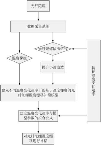
[0029] The implementation process of the fiber optic gyroscope temperature drift modeling method of the present invention is as follows figure 1 As shown, it mainly includes the following four steps:

[0030] (1) Obtain learning samples and perform denoising processing on learning samples

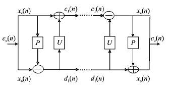
[0031] Select the learning sample set. The learning sample data obtained in this example is realized through a single-axis rate turntable with a temperature control box and a data acquisition system: first, the gyro is fixed on the turntable through a fixture, and then within the normal operating temperature range of the fiber optic gyroscope Collect the output signals at multiple sets of characteristic temperature change rates (1°C / m, 5°C / m, 8°C / m, 10°C / m), as well as the external ambient temperature and the internal working temperature of the fiber optic gyroscope shell. After obtaining the original output signal of the fiber optic gyroscope, the original output signal is filtered by lif...


PUM


Abstract

The invention discloses a method for modeling and error compensation of temperature drift of a fiber optic gyroscope, which comprises the following steps of: obtaining a learning sample and denoising the learning sample; establishing a fiber optic gyroscope temperature drift error compensation model based on temperature gradient; establishing a parameter formula based on a temperature change rate so as to determine the relations between the temperature change rate and various parameters of the fiber optic gyroscope temperature drift error compensation model; and subtracting a temperature drift compensation value, obtained by the fiber optic gyroscope temperature drift error compensation model, from the real-time output data of the fiber optic gyroscope to realize temperature compensation to the fiber optic gyroscope. The invention not only realizes modeling for the temperature drift of the fiber optic gyroscope in mechanism, but also simultaneously and greatly improves the convenience and accuracy of modeling, and has important significance to performance research and improvement of the fiber optic gyroscope in constantly variable temperature environments.

Description

technical field [0001] The invention relates to a fiber optic gyroscope in the inertial technical field, in particular to a temperature drift error modeling method of an interference fiber optic gyroscope, which is applicable to various fiber optic gyroscopes. Background technique [0002] High-precision real-time estimation of platform motion errors is a prerequisite for suppressing and compensating remote sensing image degradation. The theory and method of error estimation based on inertial sensitive devices is an effective way to solve this problem. In-depth research on the error formation mechanism, modeling and calibration methods of inertial sensors will ensure the accuracy of the measurement system from the perspective of the front-end sensor device of the error source of the measurement system. [0003] Fiber optic gyroscope is an inertial sensitive device widely used at present, so it is of great significance to study the error formation mechanism, modeling and cal...

Claims


Application Information

Patent Timeline
Patent Type & Authority Applications(China)
IPC IPC(8): G01C19/64
Inventor 陈熙源申冲
Owner SOUTHEAST UNIV
Why Eureka
Try Eureka