Device for controlling traffic signal with commercial wireless communication network

A wireless communication and traffic signal technology, applied in the direction of traffic signal control, wireless communication, wireless communication services, etc., can solve problems such as inconvenience

Inactive Publication Date: 2011-06-22
任立蓬
View PDF0 Cites 2 Cited by
  • Summary
  • Abstract
  • Description
  • Claims
  • Application Information

AI Technical Summary

Problems solved by technology

[0002] The current traffic signals are controlled by wires. In case of a traffic incident, the traffic police need to go to the scene to control it, which is very inconvenient

Method used


Image

  • Device for controlling traffic signal with commercial wireless communication network
  • Device for controlling traffic signal with commercial wireless communication network

Examples


Embodiment Construction

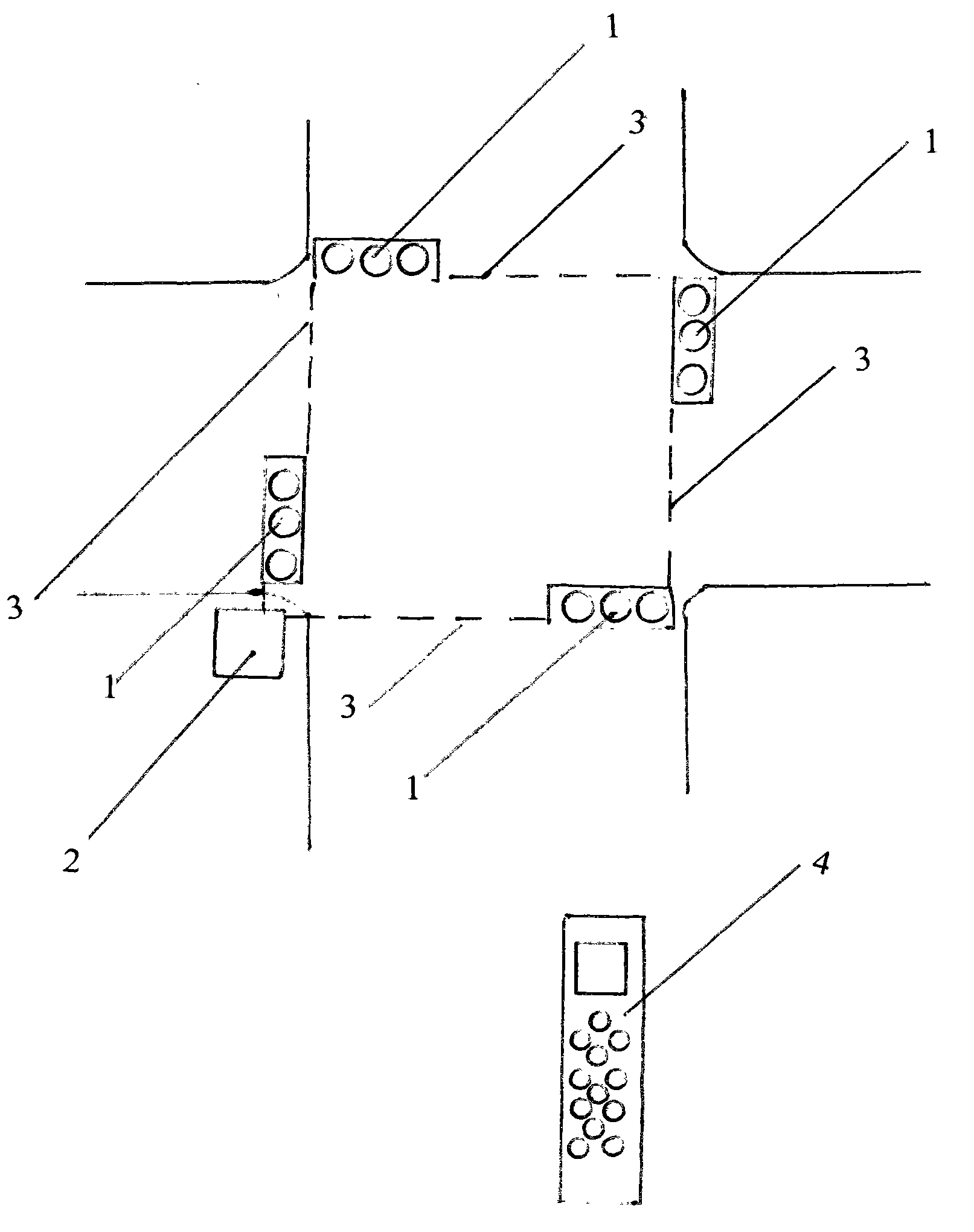
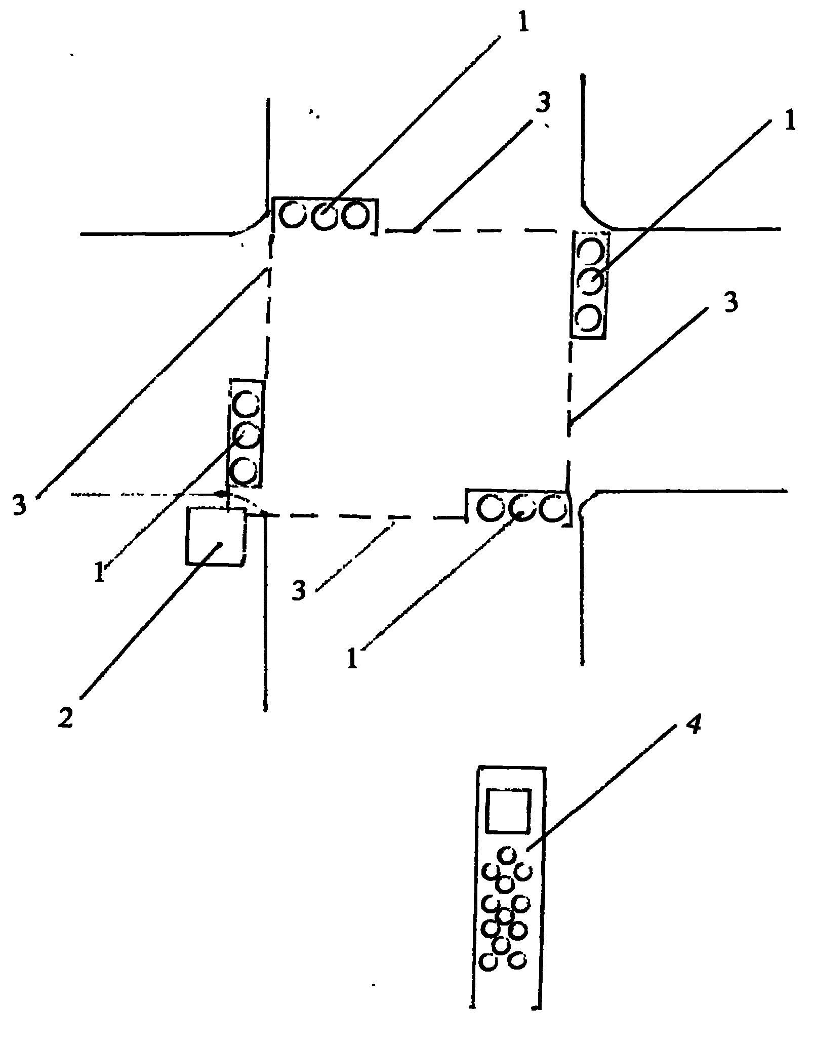
[0005] At the traffic signal site, a receiver 2 that can receive commercial wireless communication signals is installed. When the mobile phone 4 using commercial wireless communication sends out a connection signal and a remote control signal, the receiver 2 receives the signal and completes the control action, and adjusts it through the connection line 3. The signal system completes the normal display of signal light 1. To prevent hacking, operations should be encrypted. The wireless receiving and control technology is a mature technology, so it will not be described here. The commercial communication network mentioned here refers to a wireless communication network that is in operation and has sufficient coverage.


PUM


Abstract

The invention relates to a device for controlling a traffic signal with a commercial wireless communication network, and the problem that on-site regulation and control requires traffic police to conduct when a traffic accident occurs so as to cause inconvenience since the current traffic signals are all controlled in a wired manner is solved. A receiver capable of receiving a commercial wireless communication signal is arranged at the traffic signal site and can control the on-off state and time of the traffic signal; and one or more traffic signals can be remotely controlled through a mobile phone.

Description

technical field [0001] The invention belongs to the field of traffic control, in particular, it is a traffic signal device controlled by a commercial wireless communication network. technical background [0002] The current traffic signals are controlled by wires. In case of a traffic incident, the traffic police need to go to the scene to control it, which is very inconvenient. Contents of the invention [0003] A receiver that can receive commercial wireless communication signals is installed at the traffic signal site and controls the traffic signal switch and time. When necessary, one or more traffic signals can be remotely controlled by a mobile phone. Description of drawings [0004] The accompanying drawing is a schematic diagram of a traffic signal device controlled by a commercial wireless communication network. detailed description [0005] At the traffic signal site, a receiver 2 that can receive commercial wireless communication signals is installed. When ...

Claims


Application Information

Patent Timeline
IPC IPC(8): H04W4/00G08G1/07G08C17/02
Inventor 任立蓬
Owner 任立蓬
Why Eureka
Try Eureka