Laterally adjustable rail fastening system

A technology for fixing mechanisms and rails, which is applied in the direction of rails, fixed rails, roads, etc., and can solve the problems of not improving adjustability and so on

Inactive Publication Date: 2012-09-26
WIRTHWEIN AG
View PDF16 Cites 0 Cited by
  • Summary
  • Abstract
  • Description
  • Claims
  • Application Information

AI Technical Summary

Problems solved by technology

However, the adjustability is not thus improved in this way, but the adjustment is fixed by means of the known tension clamp SKL 15

Method used


Image

  • Laterally adjustable rail fastening system
  • Laterally adjustable rail fastening system
  • Laterally adjustable rail fastening system

Examples


Embodiment Construction

[0029] The following identical or functionally identical components have the same reference numerals.

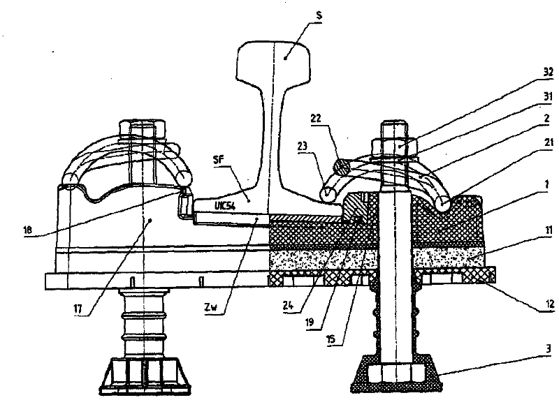
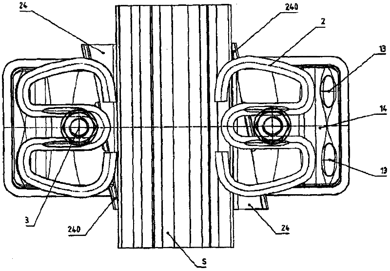
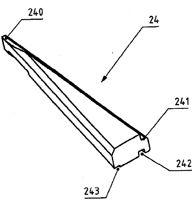
[0030] figure 1 and figure 2 The shown highly elastic support points are known in principle from WO 2005 / 073466 A1; the contents of this patent application publication which are useful for understanding the present embodiment are hereby incorporated by reference. The present embodiment has gauge adjustment in addition. The base plate 1 (possibly with additional elastic or reinforcing plates 11 , 12 ) is fastened to concrete sleepers (not shown) by means of cast-in bushings and integral sleeper bolts 3 . The UIC54-type rail S rests with a rail foot SF with a rail pad ZW in between, on a base plate 1 which, in principle cross-section, is configured like a rib plate with ribs 17, 16, In this case, however, it is not forged or rolled from steel, but injection-molded from plastic. Between the rail base SF and the ribs 17, 16 there is a wedge 24 ( Figure 3a , 3b ).

[003...


PUM


Abstract

The invention relates to a rail fastening system on a sleeper, comprising fastening screws and loop-type tension clips (2, 200), wherein the gauge can be horizontally adjusted in a continuous fashion by means of wedge elements (24, 224). The rails (S, S1) are arranged on a ribbed plate (1, 100) the ribs (16, 17, 116, 117) of which extend at an angle to the rail and a wedge (24, 224) is interposedbetween the rail base (SF) and the ribs (16, 17, 116, 117) and is mobile in the longitudinal direction of the rail. The wedge is preferably guided on the bearing (1, 100).

Description

technical field [0001] The present invention relates to a track fixing mechanism on a sleeper using a fixing bolt and an annular tension clamp, wherein the track gauge can be adjusted horizontally and continuously by means of a wedge. Background technique [0002] A number of variants are known in the prior art which roughly correspond to the type described. [0003] For example, with the wedge-shaped angular gauge plate of the system according to patent application publication DE 33 24 225 A1, track tolerances or gauge tolerances can be continuously compensated by approximately at most + / −10 mm. This wedge-shaped angle gauge stop is used in concrete sleepers or slab tracks (Festen Fahrbahn). After the two wedges are continuously adjusted relative to each other to the correct gauge, the adjustable piece away from the track is secured by tension clamps. The disadvantage here is that the system can only be used for rigid rail support points and does not permit dynamic loadin...

Claims


Application Information

Patent Timeline
Patent Type & Authority Patents(China)
IPC IPC(8): E01B9/48E01B9/30
CPCE01B9/66E01B9/30E01B9/483E01B9/48
Inventor 乔克雷姆·苏斯乌多·沃斯维恩
Owner WIRTHWEIN AG
Why Eureka
Try Eureka