
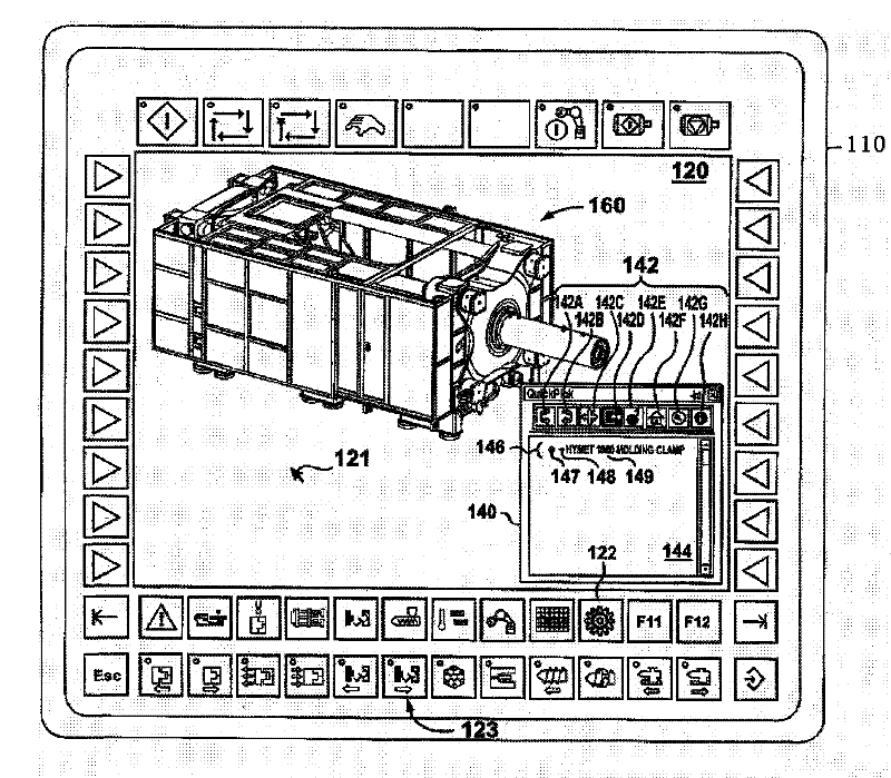
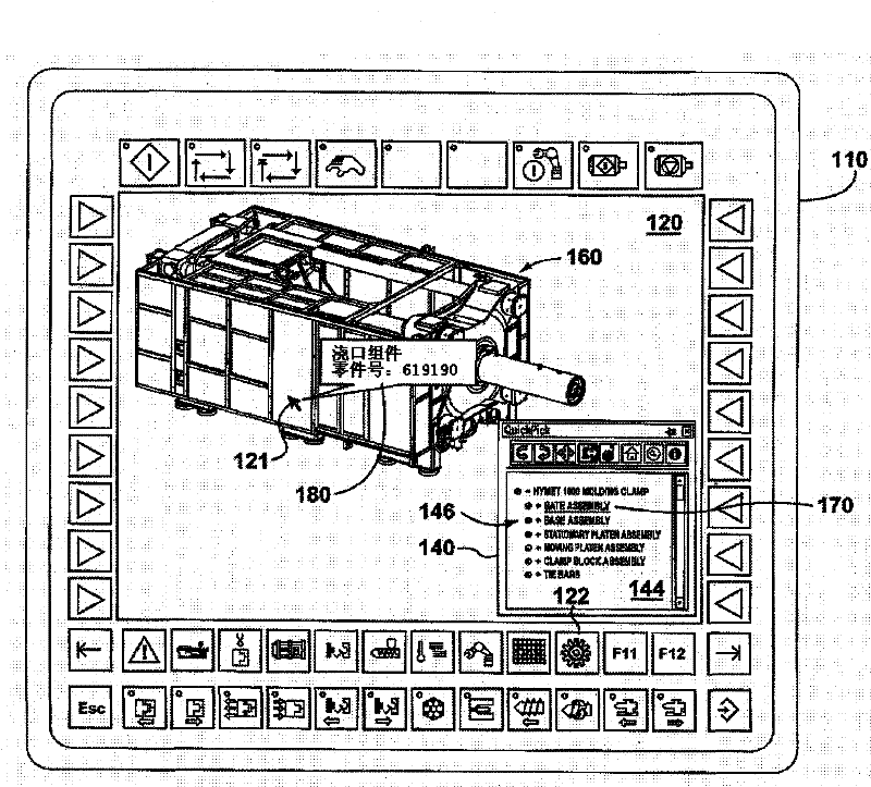
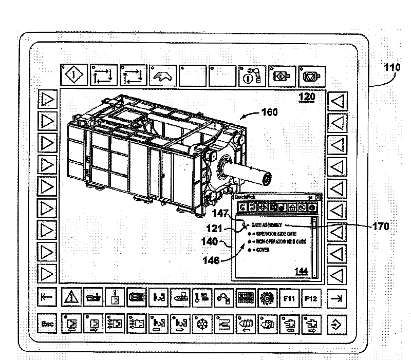
A method for displaying a virtual model of a molding system, and part information for a selected entity model, on a display of a human-machine interface of a molding system computer

A technology of human-machine interface and virtual model, which is applied in the fields of detailed information related to graphical user interface, calculation, general control system, etc., and can solve problems such as having enough time to distinguish parts with similar appearance

Inactive Publication Date: 2011-07-20
HUSKY INJECTION MOLDING SYST LTD
View PDF2 Cites 5 Cited by
  • Summary
  • Abstract
  • Description
  • Claims
  • Application Information

AI Technical Summary

Problems solved by technology

In other cases, the operator simply cannot have enough time to distinguish between similar-looking parts, so the operator will choose the advantageous, but expensive, ordering route, versus the route needed to secure the part

Method used


Image

  • A method for displaying a virtual model of a molding system, and part information for a selected entity model, on a display of a human-machine interface of a molding system computer
  • A method for displaying a virtual model of a molding system, and part information for a selected entity model, on a display of a human-machine interface of a molding system computer
  • A method for displaying a virtual model of a molding system, and part information for a selected entity model, on a display of a human-machine interface of a molding system computer

Examples


Embodiment Construction

[0027] introduction

[0028] In order to help the operator effectively and more accurately obtain the information of the required parts of the relevant mold system, various structures and steps will be described in the follow-up, which provides a virtual model for displaying the mold system and the mold connected to the mold system On the display of the man-machine interface of the system computer, the part information related to the selected entity mold of the virtual model is displayed.

[0029] Mold system

[0030] In the following description, non-limiting examples of mold system 30, such as Figure 14 and 15 As shown, a mold clamp 32 for manipulating a mold 36 and an injection unit 34 for supplying molding material to the mold 36 are included. The structure and operation of the aforementioned parts of the mold system 30 are well known in the art and thus will not be described in detail here. However, the term "mold system" as used in the following claims is intend...


PUM


Abstract

Embodiments of the present invention teach a human-machine interface of a molding system computer for displaying a virtual model of a molding system and part information for a selected entity model on a display of a human-machine interface of a molding system computer, amongst other things.

Description

technical field [0001] The present invention generally relates to, but is not limited to, mold systems, and more particularly the invention relates to, but not limited to, a man-machine interface for a mold system computer, a method executable in a mold system computer, a method in A method executable in a supplier computer, and a mold system computer that cooperates with the mold system, and others. Background technique [0002] Operators who work with molding machines (eg, molding machine engineers, maintenance personnel, and the like) may periodically require information on specific parts of the molding system. For example, an operator may need the part numbers of the parts of the mold system in order to order related replacement parts. As a further example, to set up a mold system for optimal production, an operator may need operational information on parts accompanying the mold system. If the operator is lucky, the part of interest may be visible or suitably available...

Claims


Application Information

Patent Timeline
Patent Type & Authority Applications(China)
IPC IPC(8): G06F3/048G06T19/00
CPCG06F3/04815G06T2219/2016G06T19/00G06T2200/24G05B2219/32128G05B2219/45244G06T2210/62G06T2219/016
Inventor 弗兰茨·斯蒂卡杰弗瑞·古
Owner HUSKY INJECTION MOLDING SYST LTD
Learn More