Edge-light type lighting device

A lighting device, edge light technology, applied in the direction of lighting devices, fixed lighting devices, parts of lighting devices, etc., to achieve the effect of suppressing uneven illumination

Inactive Publication Date: 2011-08-24
SUMITOMO CHEM CO LTD
View PDF13 Cites 9 Cited by
  • Summary
  • Abstract
  • Description
  • Claims
  • Application Information

AI Technical Summary

Problems solved by technology

[0006] However, since the above-mentioned directly-under-type lighting device has a structure in which the substrate on which the LED light source is mounted must be arranged parallel to the ceiling or wall on which the lighting device is installed, a certain degree of thickness is required.

Method used


Image

  • Edge-light type lighting device
  • Edge-light type lighting device
  • Edge-light type lighting device

Examples


Embodiment Construction

[0026] For the edge light type lighting device of the present invention, while referring to the appended Figure 1 While describing, the embodiments of the present invention are not limited thereto.

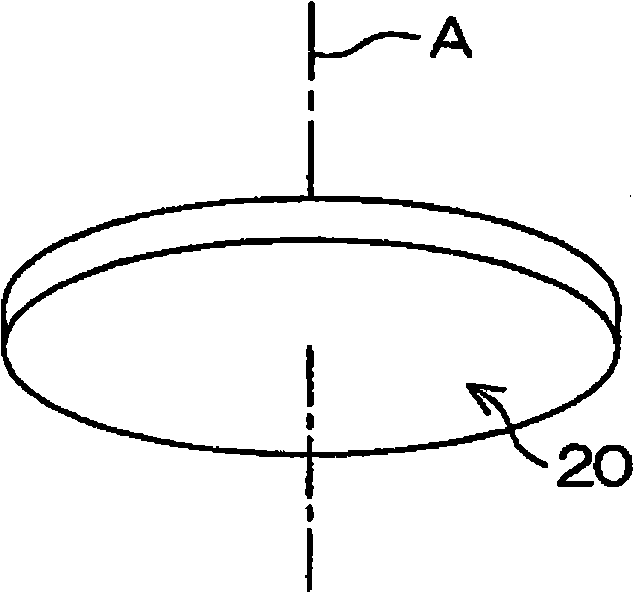
[0027] figure 1 It is a perspective view showing the appearance of the edge-light lighting device 20 . The edge-light lighting device 20 is generally in the shape of a low cylinder (hence, a circular plate having a certain thickness), and is used for, for example, a chandelier mounted on a ceiling, a wall lamp mounted on a wall, and the like. Among them, A represents the center line of the cylinder.

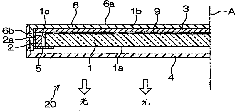
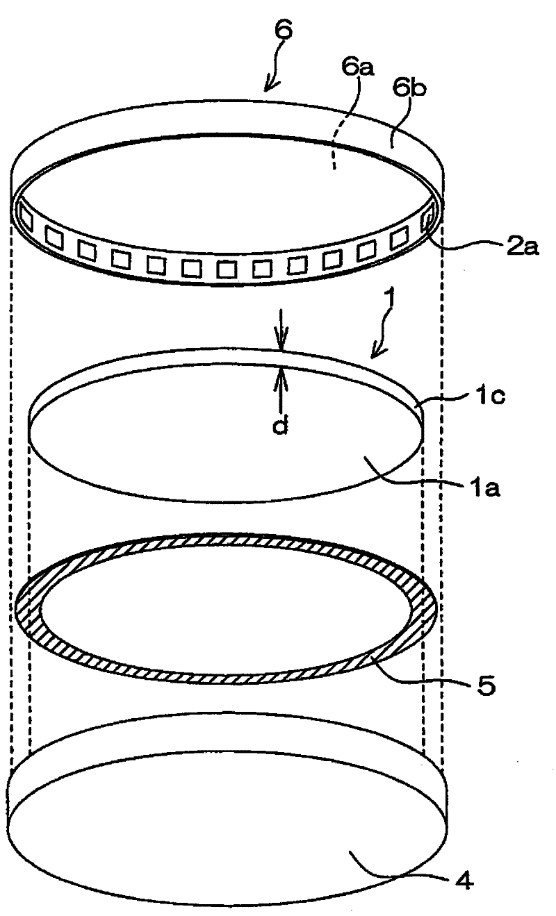
[0028] figure 2 It is a cross-sectional view schematically showing the inside of the edge-light lighting device 20 cut along a plane including the centerline A. FIG. The edge light lighting device 20 has a light guide plate 1 and an LED light source 2 . The light guide plate 1 presents an upper and lower circular plate surface parallel to each other, and a parallel band-shaped...


PUM


Abstract

The invention provides an edge-light type lighting device characterized by use of LEDs as light sources, sufficient illumination, and capability of being manufactured into a thin type. The edge-light type lighting device is provided with: a light guide plate (1) similar to a circular plate shape; LED light sources (2) arranged from the circumferential end surface of light guide plate (1) toward the internal of the light guide plate (1) according to an outgoing direction and surrounding the circumferential end surface; a reflection surface (1b) at a side opposite to a light-outgoing surface of the light guide plate making light guided from the LED light sources (2) to the light guide plate (1) outgo, reflection sheets (3) configured in a mode of covering the light guide plate (1); a frame body (6); and a light diffuse reflection part (9) formed at the surface of the reflection surface (1b) of the the light guide plate (1) and making light in diffuse reflection.

Description

technical field [0001] The present invention relates to an edge light lighting device that injects light from LEDs (light emitting diodes) into a light guide plate from a peripheral end surface of a circular light guide plate, and emits light from the front surface of the light guide plate. This edge-light lighting device is particularly useful as a lighting device to be installed on the ceiling or wall of an office or a living room. Background technique [0002] In recent years, from the viewpoint of energy saving, lighting devices using LEDs (Light Emitting Diodes) as light sources have been developed and commercialized. For example, in the case of a lighting device (chandelier) installed on the ceiling, the LED light source is installed with its outgoing surface facing vertically downward, and a milky white light-transmitting plate is installed directly below the LED light source. The light emitted from the LED light source transmits or diffuses in the light-transmitting...

Claims


Application Information

Patent Timeline
Patent Type & Authority Applications(China)
IPC IPC(8): F21S8/00F21V8/00F21V7/00F21V29/00F21V19/00F21Y101/02
CPCA42B1/004A42B1/02A42B1/241D10B2501/0632F24H1/122
Inventor 岩崎克彦小山浩士川边一成
Owner SUMITOMO CHEM CO LTD
Why Eureka
Try Eureka