
Lighting device

A lighting device and mounting technology, applied in image communication, electrical components, etc., can solve the problems of illumination fluctuation, uneven image density, uneven illumination distribution, etc., and achieve the effect of suppressing shadows

Active Publication Date: 2009-12-30
RICOH KK
View PDF9 Cites 2 Cited by
  • Summary
  • Abstract
  • Description
  • Claims
  • Application Information

AI Technical Summary

Problems solved by technology

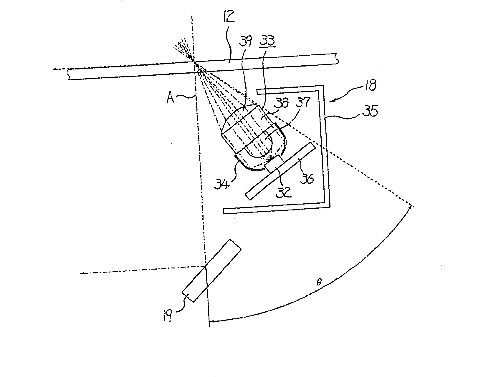
[0007] When a point light source is used as a light source, since a plurality of point light sources are arranged linearly in the main scanning direction (reading line direction), if the light emitted from each point light source directly irradiates the reading surface such as the document surface , illuminance fluctuations (uneven illuminance distribution) occur in the main scanning direction, and image density unevenness caused by illuminance fluctuations occurs when an image is formed based on the read image data.

Method used


Image

  • Lighting device
  • Lighting device
  • Lighting device

Examples


Embodiment Construction

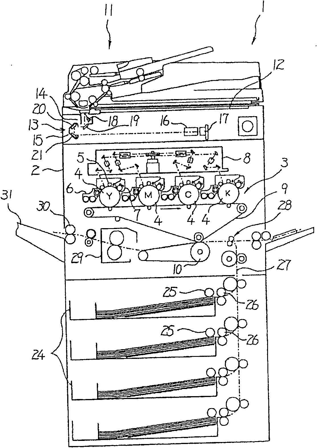
[0183] according to Figure 1~4 A first embodiment of the present invention will be described. figure 1 It is a schematic front view showing the internal structure of a color copier 1 as an image forming apparatus to which the present invention is applied.

[0184]An image forming unit 3 for forming a color image is provided at the center of the main body 2 of the copier 1 . The image forming section 3 includes four drum-shaped photoreceptors 4 that are separated at equal intervals and arranged side by side in the horizontal direction. The charging roller 5 for the agent image, the developing device 6, the cleaning device 7, the exposure device 8 for forming an electrostatic latent image by exposing the outer peripheral surface of the similarly charged photoreceptor 4 with laser light according to the image data, and the exposure device 8 for forming an electrostatic latent image by exposing The intermediate transfer belt 9 that transfers the toner images on the outer periph...


PUM


Abstract

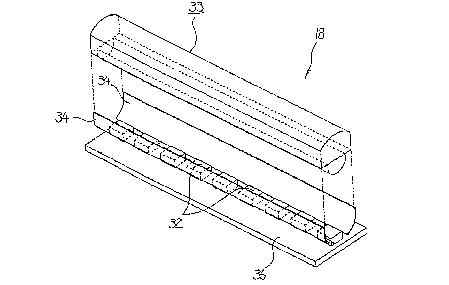
The invention discloses a lighting device, image reading apparatus, and image forming apparatus, which can effectively utilize a light quantity of a point source when a point source with little light quantity is used as a light source of a reading device. A lighting system is provided with a point source 32 emitting light to the surface of a document which is located on contact glass 12 and becomes a reading object, and a condensing body 33 which is arranged forward in the direction of emission of light emitted from the point source 32 and which condenses light emitted from the point source 32 within a reading width in the direction of a sub-scanning direction at the time of document reading. The condensing body 33 is arranged in a direction in which angles of all lights passing through the condensing body 33 are less than a critical angle '[theta]' totally reflected by the contact glass 12. Thus, all of the lights emitted from the point source 32 through the condensing body 33 are irradiated to the surface of the document without total reflection at the contact glass 12, thereby enabling all of the lights emitted from the point source 32 to be effectively used for lighting the document surface.

Description

[0001] The present invention is a divisional application of an invention patent application with an application date of August 19, 2004, an application number of 200410064131.2, and an invention title of "illumination device, image reading device and image forming device". technical field [0002] The invention relates to an illuminating device, an image reading device and an image forming device. Background technique [0003] Conventionally, an image reading device such as a scanner has a light source that emits light onto a document surface of a document to be read on a contact glass, and the reading light that travels along the reading optical axis after being reflected by the document surface passes through a lens and passes through the lens. The original image is imaged on the photoelectric conversion device (CCD) and read. [0004] As a light source of such an image reading device, rod-shaped light sources such as fluorescent lamps and xenon lamps, and point light sour...

Claims


Application Information

Patent Timeline
Patent Type & Authority Patents(China)
IPC IPC(8): H04N1/028
Inventor 樱井靖夫河内雅史
Owner RICOH KK
Learn More