Collocation method of bicycle center shafting loss resistance

A configuration method and wear-resistant technology, which is applied to vehicle components, vehicle gearboxes, chain/belt transmissions, etc., to achieve the effect of easy modification, convenient disassembly, and simple configuration structure

Active Publication Date: 2013-01-09
南通同旭贸易有限公司
View PDF4 Cites 0 Cited by
  • Summary
  • Abstract
  • Description
  • Claims
  • Application Information

AI Technical Summary

Problems solved by technology

These, through a continuous vicious cycle, eventually lead to the above failure

Method used


Image

  • Collocation method of bicycle center shafting loss resistance
  • Collocation method of bicycle center shafting loss resistance
  • Collocation method of bicycle center shafting loss resistance

Examples


Embodiment Construction

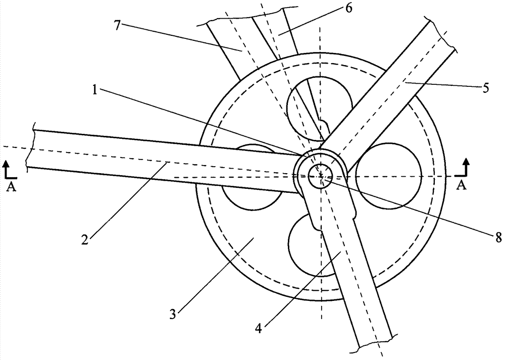
[0017] in the attached figure 1 , 2 In the shown structural view of the embodiment of the present invention: the cylindrical right bearing sleeve 1 is connected with the right end of the front fork of the rear fork beam 2 made into an "H" shape, and the right end of the lower fork of the front inclined beam 5 is connected as One body; the chain plate 3 is located between the right bearing housing 1 and the left bearing housing 9, and is a tight fit structure with the central shaft 8; the right crank 4 and the right end of the central shaft 8 are pin tight fit; the left crank 6 and the central shaft 8 The left end of the pin is a tight fit; the left end of the front fork of the "H" shaped rear fork beam 2, the left end of the lower fork of the front slant beam 5 and the lower end of the rear slant beam 7 are connected with the cylindrical left bearing seat sleeve 9 as one.

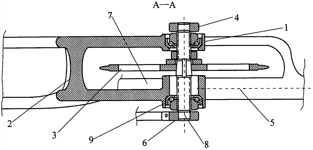
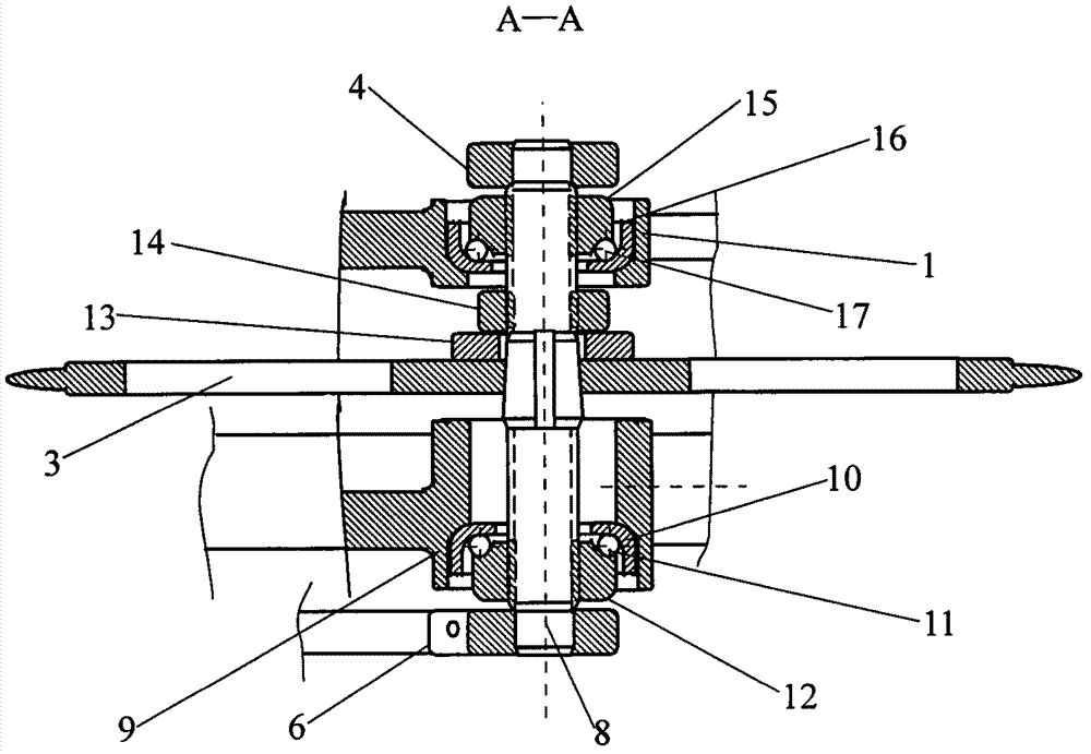
[0018] in the attached figure 2 , 3 In the shown cross-sectional view of the structure of the embod...


PUM


Abstract

The invention discloses a collocation method of bicycle center shafting loss resistance. Right bearing inner races of a center shaft extends to a near right end of the center shaft; at the right side of a keyboard, and at the position closing to the right side face of the keyboard, the keyboard and the center shaft are arranged into a whole, and are arranged between the two right bearing inner races of the center shaft; a rear fork is manufactured into an H shape; a center shaft sleeve seat is divided into a left part and a right part, namely a left bearing sleeve seat and a right bearing sleeve seat respectively corresponding to the left bearing inner race and the right bearing inner race of the center shaft; and a front fork right support end of an H-shaped rear fork bridge, a lower fork right support end of a front oblique beam and a cylindrical right bearing seat sleeve are connected into a whole, and a front fork left support end of the H-shaped rear fork bridge, a lower fork left support end of the front oblique beam and a cylindrical left bearing seat sleeve are connected into a whole, thus the keyboard is positioned between the two bearings to form a lever mode of single force point-two-side support point.

Description

technical field [0001] The invention relates to a configuration method for a central axis system of a bicycle or an electric bicycle. Background technique [0002] At present, the central shaft system configurations of known bicycles or electric bicycles are all system configurations in which the shaft matching structure is placed in the middle and the chain disc is placed on the right side. This configuration method is mature and has formed a fixed mechanism mode, so that it has long been used as the implementation standard of quite a few manufacturers. However, countless bicycle and electric bicycle failures, such as premature bottom bracket failure, premature bearing failure, premature chain plate failure, chain drop, flywheel damage, etc., are directly or indirectly related to this configuration mode. Because of the two fulcrum-one-side force point leverage mode formed by this configuration, the rearward pulling force of the transmission chain is almost entirely applied...

Claims


Application Information

Patent Timeline
Patent Type & Authority Patents(China)
IPC IPC(8): B62M9/02B62M9/00
Inventor 屈百达
Owner 南通同旭贸易有限公司
Why Eureka
Try Eureka