Fully integrated hydraulic clutch

A technology for clutches and pressure plates, applied in clutches, fluid-driven clutches, non-mechanical-driven clutches, etc., can solve the problems of high possibility of errors and complicated implementation, and achieve the effects of improving efficiency, avoiding conversion losses, and simplifying assembly

Active Publication Date: 2018-08-03
SCHAEFFLER TECH AG & CO KG
View PDF8 Cites 0 Cited by
  • Summary
  • Abstract
  • Description
  • Claims
  • Application Information

AI Technical Summary

Problems solved by technology

Most of these known clutch systems also have the disadvantage that during assembly, because the clutch system is often only assembled at the customer (OEM), the possibility of error is relatively high
These known systems are also usually quite complex to implement

Method used


Image

  • Fully integrated hydraulic clutch
  • Fully integrated hydraulic clutch

Examples


Embodiment Construction

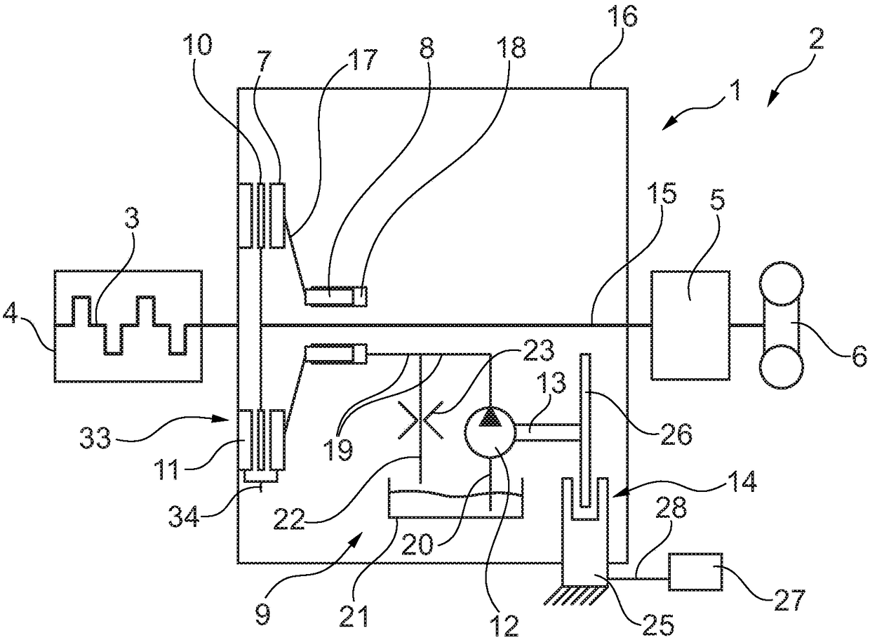
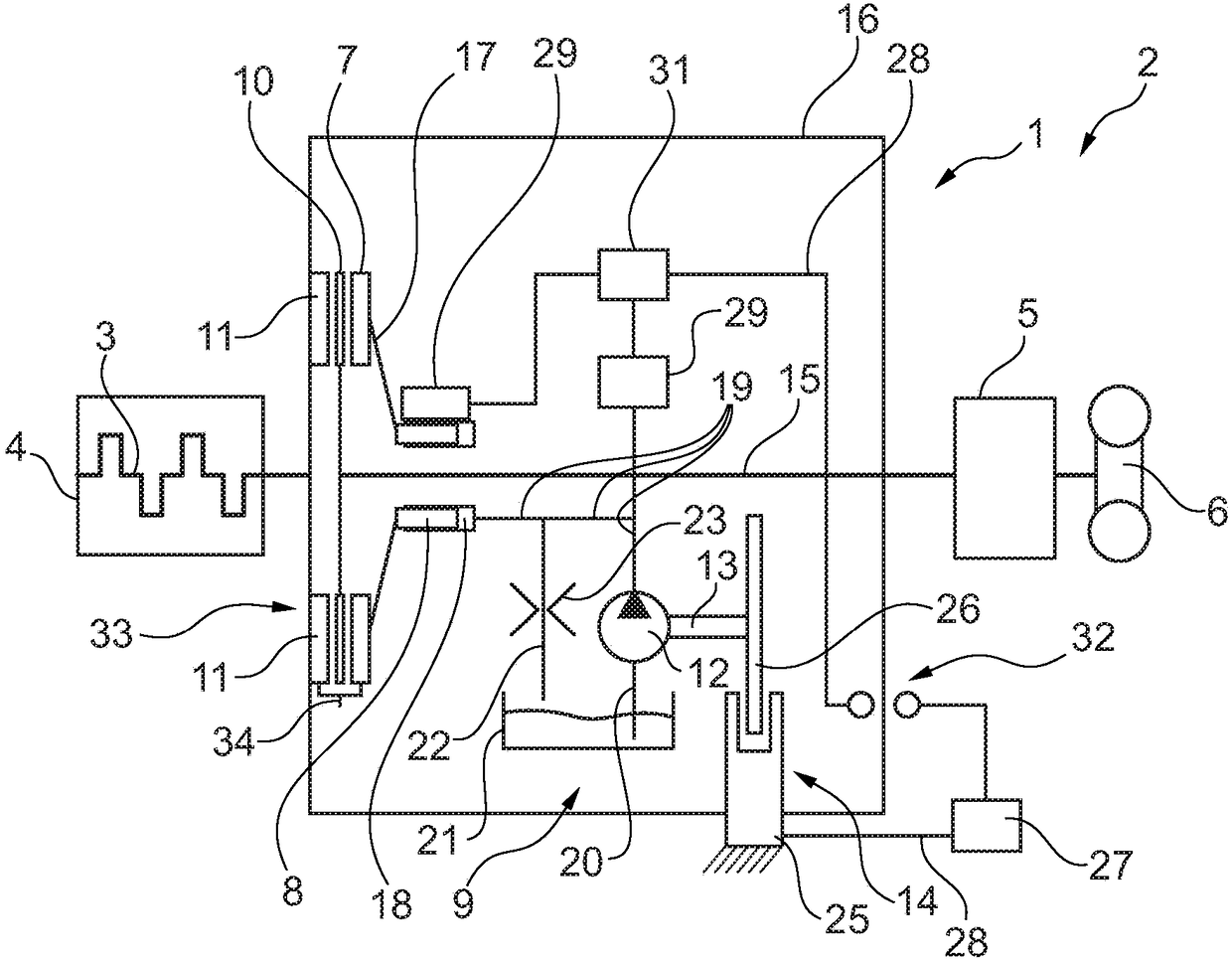
[0026] exist figure 1 with 2 Two embodiments of the clutch device 1 according to the invention are shown in . Each clutch device 1 is provided for incorporation into a drive train 2 of a motor vehicle, such as a passenger car, truck, bus or agricultural truck. The clutch device 1 serves as a detachable coupling element for the selective transmission of torque from a crankshaft 3 of an internal combustion engine 4 (diesel or petrol engine) to a transmission 5 which is connected to a wheel 6 or wheels of a motor vehicle. 6 motion coupling.

[0027] The clutch device 1 has a pressure plate 7 which is movable in the axial direction of the clutch device 1 (the axial direction corresponds to the direction along the clutch axis of rotation / rotation axis of the clutch). The pressure plate 7 here interacts / kinematically couples in the usual manner with the actuating piston 8 of the actuating device 9 . The pressure plate 7 can move back and forth between an actuated position (here ...


PUM


Abstract

The invention relates to a clutch device (1) for the drive train (2) of a motor vehicle, having at least one pressure plate (7) that preferably is movable in an axial direction of the clutch device, wherein the pressure plate interacts with an actuating piston (8) of an actuating device (9) and can be moved back and forth between a coupled position and an uncoupled position, and wherein the actuating device has a pump (12). Said pump has a pump drive shaft (13) and controls a pressure level influencing the position of the actuating piston for adjusting the pressure plate. The pump drive shaft interacts with a braking system (14) in at least one activated state of the braking system such that for pressurizing the actuating piston with a first pressure level, the pump is driven by the pump drive shaft.

Description

technical field [0001] The invention relates to a clutch arrangement (implemented as a single clutch module or a double clutch module) for a drive train of a motor vehicle, such as a passenger car, a motorcycle, a truck, a bus or an agricultural truck, which clutch arrangement has at least A pressure plate, preferably movable in the axial direction of the clutch device (wherein the pressure plate presses the clutch output disk against a counter-pressure plate connectable to the crankshaft of the internal combustion engine in the engaged position of the clutch device), wherein the The pressure plate cooperates with an actuating piston of the actuating device and is movable back and forth between an engaged position and a disengaged position, and the actuating device has a pump with a pump drive shaft and controls the pressure level affecting the position of the actuating piston for adjusting the pressure plate. Background technique [0002] Similar clutch devices / clutch syste...

Claims


Application Information

Patent Timeline
Patent Type & Authority Patents(China)
IPC IPC(8): F16D25/0635F16D25/12F16D48/02
CPCF16D48/02F16D2048/0233F16D2048/026
Inventor D·赫尔科默M·格雷特勒M·贝尔
Owner SCHAEFFLER TECH AG & CO KG
Why Eureka
Try Eureka