Plasma display panel (PDP) terminal hot-pressing head structure

A screen terminal and indenter technology, which is applied in the field of PDP screen terminal hot-pressing indenter structure, can solve the problems of improved, limited, and unmanufactured pressure distribution without indenter, and achieve the effect of sufficient pressure uniformity.

Inactive Publication Date: 2011-09-07
SICHUAN COC DISPLAY DEVICES
View PDF5 Cites 3 Cited by
  • Summary
  • Abstract
  • Description
  • Claims
  • Application Information

AI Technical Summary

Problems solved by technology

[0003] For the heat-pressing devices in the prior art, such as "Automatic pressure recognition device for PDP panel heat-pressing equipment" (application number: 200820229582.0), the patent describes the pressure control system for the heat-pressing head of the PDP panel, but this The invention patent is still limited to the single pressure head pressure control mode. Although the overall pressure control becomes effective, the local pressure control of the pressure head still cannot be improved;
[0004] Another patent "thermocompression bonding device and thermocompression bonding method" (application number: 20041085873.3), this patent invented a new indenter structure of the LCD display, this structure can be very fast when the electrode terminal is thermally pressed. Good distribution of the pressure on the electrode terminals, but the indenter system is complicated, maintenance, repair, and debugging are difficult, and it does not have good manufacturability in the actual use of the production line;
[0005] In addition, in the patent "Hot Pressing Equipment and Its Hot Pressing Device" (Application No.: 200810000492.9), this patent mainly improves the temperature control system of the hot pressing head, but does not improve the pressure distribution of the pressing head

Method used


Image

  • Plasma display panel (PDP) terminal hot-pressing head structure
  • Plasma display panel (PDP) terminal hot-pressing head structure
  • Plasma display panel (PDP) terminal hot-pressing head structure

Examples


Embodiment Construction

[0030] The present invention will be further described below in conjunction with accompanying drawing by embodiment:

[0031] preferred embodiment

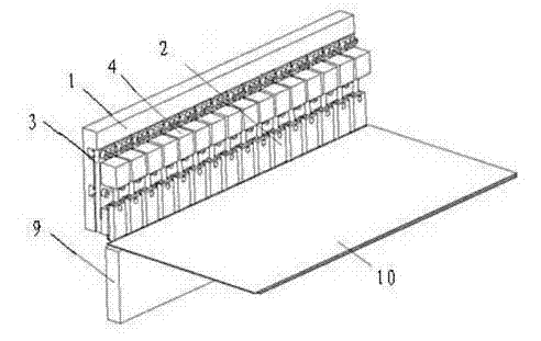
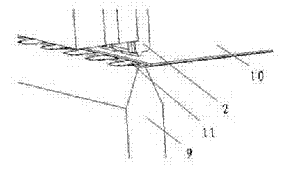
[0032] like figure 1 and figure 2 As shown, the action process of the indenter of the present invention is as follows: during hot pressing, the base 1 descends with the moving mechanism of the equipment, and moves toward the hot pressing support seat 9 until the indenter 2 presses the screen 10 and the TCP11 on it, and then the pressing device 4 produces thrust and provides to pressure head 2, the TCP11 on the screen 10 (such as Figure four As shown), the hot pressing action is realized. After the completion, the pressure device 4 is retracted, the pressure on the pressure head 2 is released, the pressure head 2 and the base 1 rise with the equipment, and finally the pressure head 2 breaks away from the TCP11 on the screen 10 , the hot pressing action is completed.

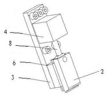
[0033] like image 3 As shown, the structure of the split...


PUM


Abstract

The invention discloses a plasma display panel (PDP) terminal hot-pressing head structure, which relates to the PDP terminal hot-pressing head structure realizing hot-pressing pressure and temperature control by distributing a plurality of pressing heads. The PDP terminal hot-pressing head structure provided by the invention aims to overcome the shortcomings of the prior art, and can effectively solve the problem of pressing head pressure and heating distribution and improve pressing head regulation processibility and pressing head maintenance operability. To fulfill the aims, the technical scheme adopted by the invention is that: the PDP terminal hot-pressing head structure comprises a base and the pressing heads; a bottom plate is detachably connected to the base by a connecting device;the PDP terminal hot-pressing head structure further comprises the plurality of pressing heads; the rear ends of each pressing head are connected with a pressure device; and the pressure devices control the actions of the pressing heads, can output constant pressure according to a set value, and are fixed on the bottom plate. The PDP terminal hot-pressing head structure is applied to tape carrierpackage (TCP) hot-pressing.

Description

technical field [0001] The invention relates to a structure of a PDP pressing head, in particular to a structure of a PDP panel terminal hot pressing head which distributes hot pressing pressure and temperature control through a plurality of pressing heads. technical background [0002] This patent invents a pressure head structure and a corresponding hot pressing method that can be applied to hot pressing of plasma (PDP) screen terminal electrodes and external flexible connecting wires. Plasma display (PDP) through ACF (English abbreviation of Anisotropic Conductive Film, hereinafter referred to as ACF) will TCP (English abbreviation of Tape Carrier Package, that is, circuit board with chip, hereinafter referred to as TCP), FPC (English abbreviation of Flexible Print Circuit , that is, flexible circuit board, hereinafter referred to as FPC) after the connection, the electrical connection between the screen and the circuit board is realized. This process is often called hot...

Claims


Application Information

Patent Timeline
Patent Type & Authority Applications(China)
IPC IPC(8): H01J9/36
Inventor 孙键昌
Owner SICHUAN COC DISPLAY DEVICES
Why Eureka
Try Eureka