Facet joint prosthesis

A facet joint and prosthesis technology, applied in the field of spinal facet joint prosthesis and spinal implants, can solve the problems of spinal instability, loss of facet joint movement restriction characteristics, etc.

Inactive Publication Date: 2011-09-07
KINETIC SPINE TECH INC
View PDF10 Cites 2 Cited by
  • Summary
  • Abstract
  • Description
  • Claims
  • Application Information

AI Technical Summary

Problems solved by technology

In these cases, although the condylar surfaces are spared further damage, the motion-limiting properties of the facet joints are lost, resulting in spinal instability

Method used


Image

  • Facet joint prosthesis
  • Facet joint prosthesis
  • Facet joint prosthesis

Examples


Embodiment Construction

[0036] In the following description, the terms "upper", "lower", "front", "rear" and "lateral" will be used. These terms are used to describe the orientation of the vertebrae or implants of the present invention when positioned in the spine and when the spine is in an upright position. Thus, "superior" refers to the top and "posterior" refers to that portion of the implant (or other spinal component) that faces the rear of the patient's body when the spine is in an upright position. Similarly, when the spine is in an upright position, the term "inferior" will be used to refer to the bottom of the implant, while "anterior" will be used to refer to those parts facing the front of the patient's body.

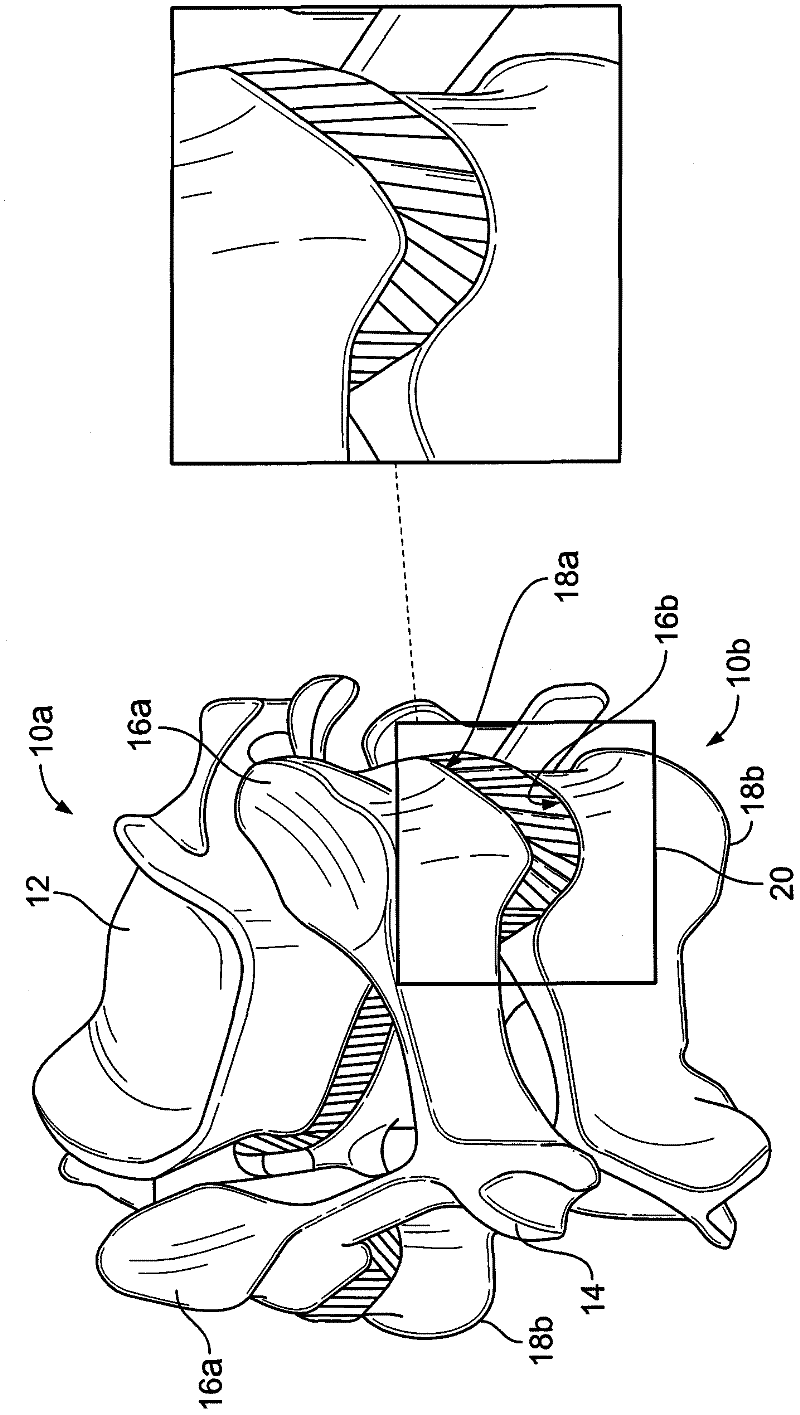
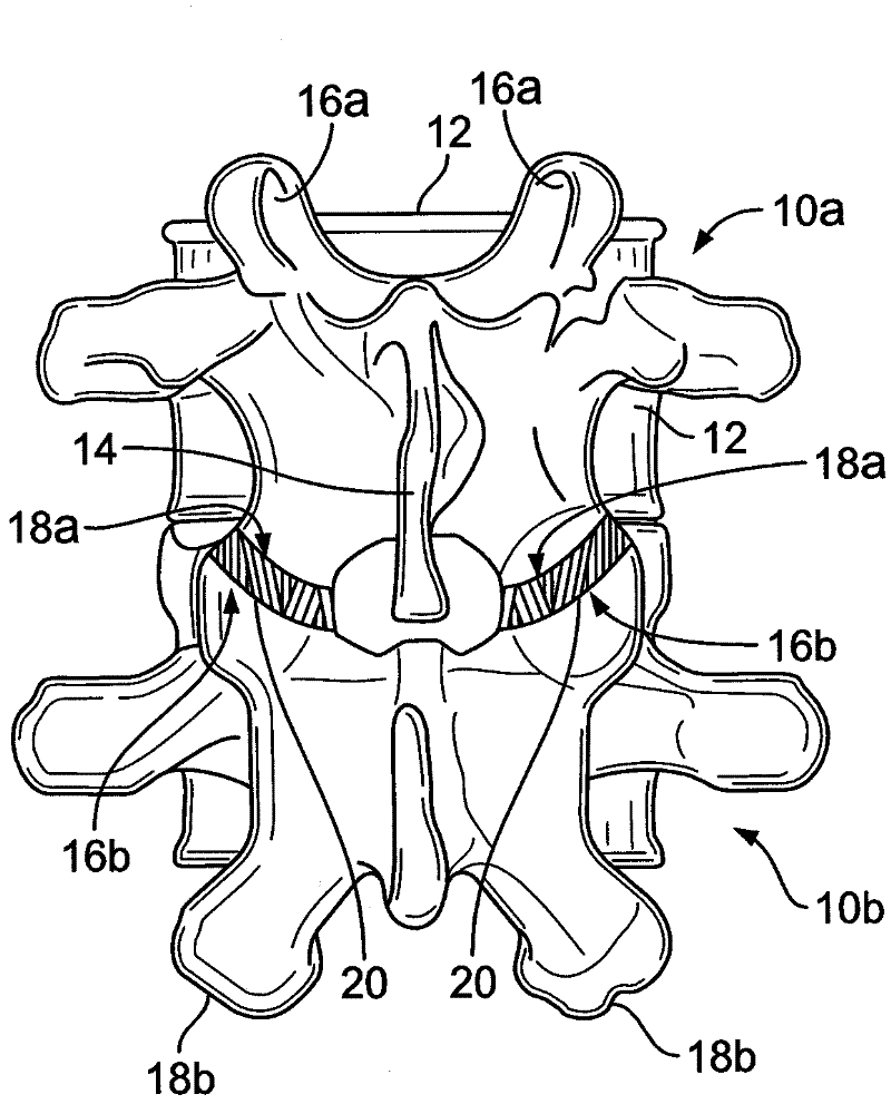
[0037] Such as figure 1 and figure 2 As shown, the spinal column segments, as that term is used herein, comprise an upper vertebra 10a and a lower vertebra 10b, respectively. Each vertebra includes a vertebral body 12 and spinous processes 14 . As indicated above, each vertebr...


PUM


Abstract

A facet joint prosthesis comprises a pair of facet elements for engaging the superior and inferior articular processes of a facet joint. The facet elements are provided with one or more articulating surfaces for articulating movement there-between. The facet elements are also provided with a positive engagement means for preventing separation of the elements and / or to limit relative movement there-between within a pre-determined range. In one aspect, the invention provides a spacer for positioning between the facet elements and for distracting the facet joint. The spacer may also serve to form an artificial lateral mass between the superior and inferior articulating surfaces. The spacer may be provided with engagement means for positively engaging one or both of the facet elements.

Description

[0001] Cross References to Related Applications [0002] This application claims priority to US Patent Application No. 61 / 106,067, filed October 16, 2008. The entire content of this prior application is incorporated herein by reference. technical field [0003] The present invention relates to artificial joint implants and, in particular, to spinal implants. More specifically, the present invention relates to spinal facet joint prostheses. Background technique [0004] The spine is a complex structure that includes various anatomical components that, although very flexible, provide structure and stability to the body. A stable spine is important to prevent incapacitating pain, progressive deformation and neurological damage. The spine is made up of vertebrae, each of which has a generally cylindrical ventral body. The opposing surfaces of adjacent vertebral bodies are joined together and separated by an intervertebral disc (or "disc"), which includes fibrocartilage mater...

Claims


Application Information

Patent Timeline
Patent Type & Authority Applications(China)
IPC IPC(8): A61F2/44
CPCA61F2002/30772A61F2310/00029A61F2002/30825A61F2220/0025A61F2002/3055A61F2310/00179A61F2002/448A61F2002/30387A61F2310/00185A61F2310/00017A61F2002/30594A61F2002/30879A61B17/7064A61F2002/4485A61F2310/00023A61F2002/30578A61F2250/0008A61F2002/304A61F2002/30663A61F2002/30662A61F2002/30553A61F2/4405A61F2002/30841A61F2/44A61B17/70
Inventor S·J·迪普莱西R·J·赫尔伯特L·塞克杭
Owner KINETIC SPINE TECH INC
Why Eureka
Try Eureka