
Facet joint prosthetic replacement and method

a facet joint and prosthetic technology, applied in the field of facet joint prosthesis and kit, can solve the problems of most significant problems facing, back pain, and impairing the functioning of the dis

Inactive Publication Date: 2010-08-19
MUHANNA NABIL L
View PDF16 Cites 51 Cited by
  • Summary
  • Abstract
  • Description
  • Claims
  • Application Information

AI Technical Summary

Benefits of technology

"The present disclosure provides a facet joint prosthesis for replacing a facet joint. The prosthesis includes a first and second pedicle screw with screw heads, an inner member with an elongated bulbous portion that tapers to a shaft via a neck portion, and a centered eyelet that receives and supports the pedicle screw head, and an outer member with an open ended elongated bulbous portion that tapers to a shaft via a neck portion. The prosthesis also includes a kit for replacing a facet joint. The technical effects of the invention include providing a facet joint prosthesis that can replace a facet joint and restore its function, as well as providing a kit for easy replacement of a facet joint."

Problems solved by technology

Back pain is one of the most significant problems facing the workforce in the
One of the most common causes of back pain stems from trauma to an intervertebral disc, resulting from mechanical shock, stress, tumors or degenerative disease, which may impair functioning of the disc and limit spinal mobility.
In many cases, the disc is permanently damaged and the preferred treatment becomes partial or total excision.
Another cause of back injury is herniation of the intervertebral disc, wherein the gelatinous fluid of the nucleus pulposus enters the vertebral canal and pressures the spinal cord.
Traumatic injury to an intervertebral disc that is not removed will frequently promote scar tissue formation.
Scar tissue is weaker than original healthy tissue so that the disc will progressively degenerate, lose water content, stiffen and become less effective as a shock absorber.
Eventually, the disc may deform, herniate, or collapse, limiting flexibility of the spinal column at that position.
The anterior approach to the spinal column is complicated by the internal organs that must be bypassed or circumvented to access the vertebrae.
Although the use of an intervertebral disc prosthesis may achieve some level of success with patients, disc replacement does not address spine pathologies such as spondylolisthesis and spinal stenosis caused by facet joint degeneration or disease

Method used


Image

  • Facet joint prosthetic replacement and method
  • Facet joint prosthetic replacement and method
  • Facet joint prosthetic replacement and method

Examples


Embodiment Construction

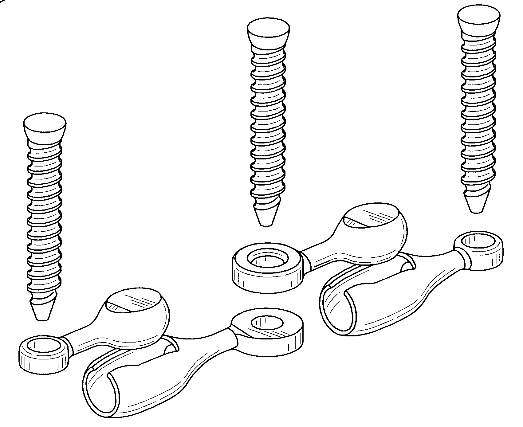
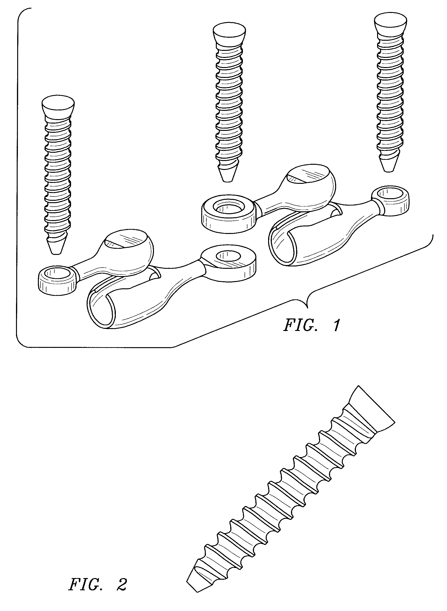
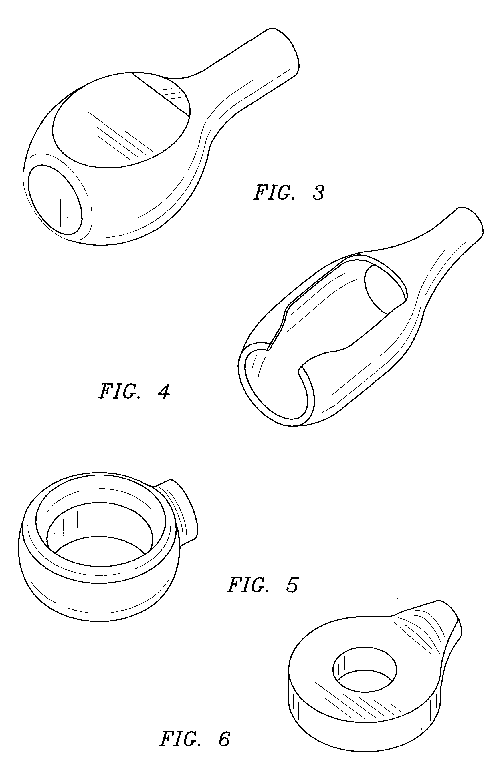
[0045]Referring generally to the figures, there is shown an assembly, and individual components, for a facet joint prosthesis. In general, the facet joint prosthesis is comprised of an inner member having a bulbous portion linked to a bulbous cavity of an outer member. The facet joint prosthesis assembly is anchored to a patient's spine by a plurality of pedicle screws inserted through eyelets that are integral to the inner and outer members.

[0046]The terms “articulate,”“articulation,” or “articulating,” as used herein, refer broadly to rotational movement and linear movement involving any combination of pitch, roll, yaw, and translational motion. Generally, rotational motion is the spinning of an object about any one of the three Cartesian axes. The three linear degrees of freedom are described in common language terms such as forward / backward, up / down, and side / side. These linear directions can also be used to define axes of rotation for rotational motion as well as axes of transl...


PUM


Abstract

The present disclosure provides prosthesis, methods, and kits for replacing a facet joint, in particular prosthesis, methods, and kits for replacing a spinal motion segment comprising a facet joint. The prosthesis includes a first and second member that interlock to form a sliding joint.

Description

CROSS REFERENCE TO RELATED APPLICATION[0001]This application claims the benefit of U.S. provisional patent application No. 61 / 152,279, filed Feb. 13, 2009.FIELD OF THE DISCLOSURE[0002]The present disclosure relates to prosthesis, methods, and kits for replacing a facet joint and, in particular, for replacing a spinal motion segment comprising a facet joint.BACKGROUND[0003]The spinal column, which is the central support to the vertebrate skeleton and a protective enclosure for the spinal cord, is a linear series of bones, or vertebrae. Intervertebral discs separate and reduce friction between adjacent vertebrae and absorb compression forces applied to the spinal column. Spinal nerves that extend from each side of the spinal cord exit the column at intervertebral forama.[0004]A typical vertebra comprises an anterior body, and a posterior arch that surrounds the spinal cord lying within the vertebral foramen formed by the arch. The muscles that flex the spine are attached to three proc...

Claims


Application Information

Patent Timeline
Patent Type & Authority Applications(United States)
IPC IPC(8): A61B17/70
CPCA61B17/7064A61F2/0095A61F2/4405A61F2002/30372A61F2002/30578A61F2310/00023A61F2002/30607A61F2002/30841A61F2220/0033A61F2250/0062A61F2002/30594
Inventor MUHANNA, NABIL L.
Owner MUHANNA NABIL L
Learn More