Facet joint prosthesis

a facet joint and prosthesis technology, applied in the field of spinal column prosthesis, can solve the problems of insufficient space, damage to the connection between vertebrae, pain, and even loss of mobility, and achieve the effects of convenient and convenient use, convenient operation, and convenient us

Inactive Publication Date: 2011-03-01
FACET LINK
View PDF22 Cites 48 Cited by
  • Summary
  • Abstract
  • Description
  • Claims
  • Application Information

AI Technical Summary

Benefits of technology

[0025]The invention further relates to a method for implanting a prosthesis comprising a retaining piece and a bearing piece, wherein the bearing piece comprises a pressure plate and, lying opposite this, a bearing insert having an articular surface for interaction with an articular surface of an adjacent vertebra, said method involving steps in which a slit is excavated on the articular process of a vertebra so as to extend from one articular surface of the vertebra in the direction of the other articular surface of the vertebra, and the guide rod is inserted into the slit, with the bearing piece coming to rest with its pressure plate on the articular surface. The method according to the invention has the advantage that only a single slit has to be formed on the vertebra. This slit can be of small dimensions, since it only has to accommodate one guide element and is not exposed to retaining forces of the prosthesis. In particular, it is possible to form the slit in the dorso-lateral direction. This p

Problems solved by technology

Back problems can often be attributed to pathological changes in the area of the spinal column.
The connection between vertebrae may become damaged because of disease or overloading, either through injury or wear.
This can lead to restricted movement, pain, or even loss of mobility.
However, it has been shown that this is not sufficient and that, in many cases, targeted therapy of the facet joints is also needed.
The absence of facet joints reduces the stability of the spinal column to a great extent and thus leads to greater loading of the other areas of the spinal column, which often leads to defects in the area of adjacent connection between vertebrae.
Here too, the biomechanics are negatively affected.
This removal of tissue often leads to an interruption of the natural supply of surrounding healthy tissue, with the consequence of necrotic changes.
As a result of this combination, the prosthesis has a complicated structure and has relatively large dimensions.
This necessitates a complex operation with an access route of large dimension.
Treatment of the facet joints in the area of the cervical spine is difficult with this prosthesis.
Since these through-holes have to be flush with one another, their creation is very difficult and requi

Method used


Image

  • Facet joint prosthesis
  • Facet joint prosthesis
  • Facet joint prosthesis

Examples


first embodiment

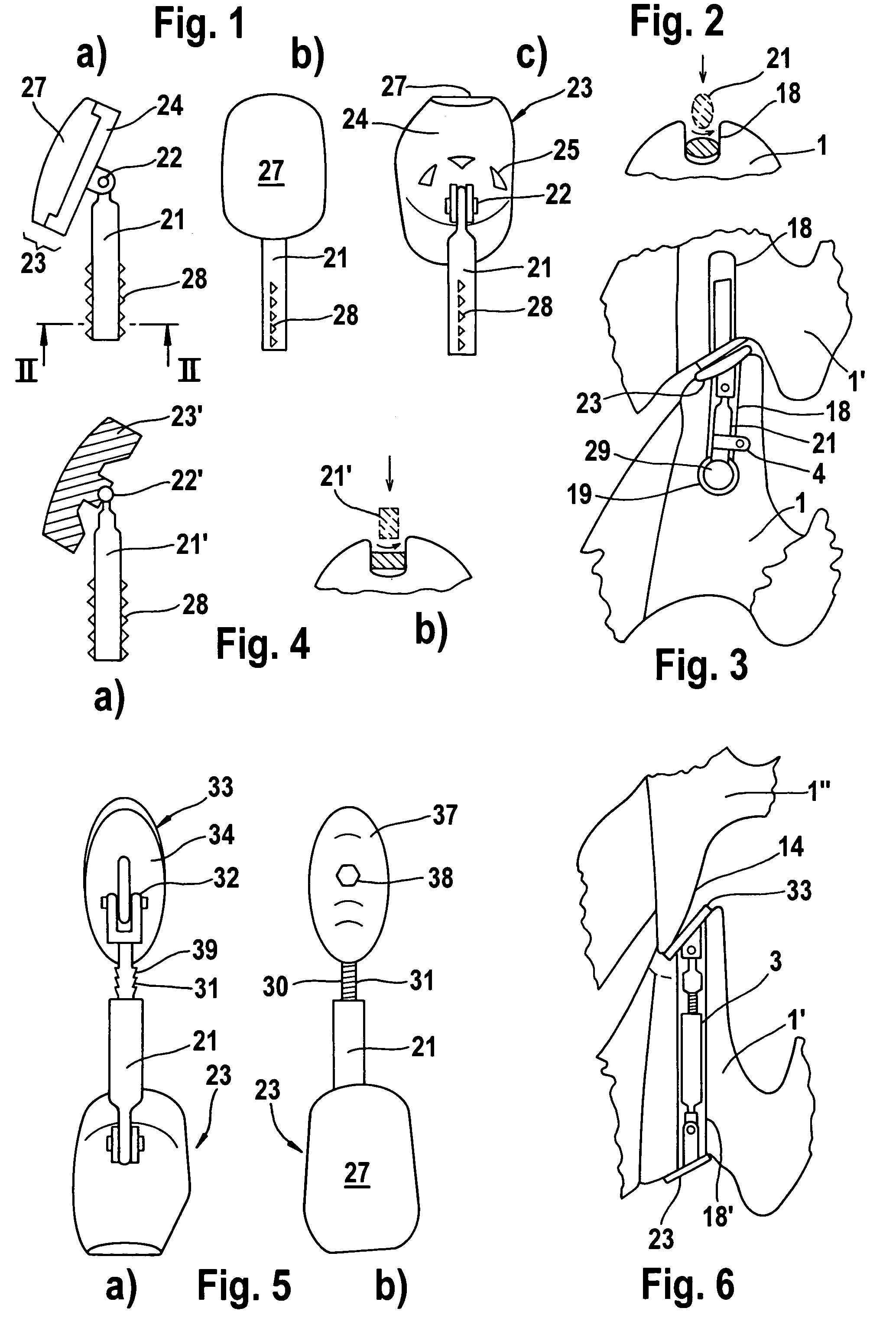
[0038]The invention envisages the replacement of articular surfaces 13, 14 that have become defective through disease or injury. a prosthesis 2 according to the invention is depicted in FIGS. 1a)-c). The prosthesis comprises a guide rod 21 which is mounted on a bearing piece 23, so as to move between different angles, via a pivot hinge 22 designed as a pin bearing. The bearing piece 23 comprises a compression plate 24 on its side directed toward the guide rod 21, and, on its opposite side, it has a bearing shell 27. The latter can be made of a plastic material that promotes sliding (for example polyethylene). Provision can optionally be made for the bearing shell 27 to be made movable in rotation on the pressure plate 24. For this purpose, the pressure plate 24 has, on its top face, a pot-shaped recess into which the bearing shell 27 is mounted via a blunt underside. However, it is also possible for the bearing shell 27 to be made of a biocompatible metal alloy, for example CoCrNi. ...

second embodiment

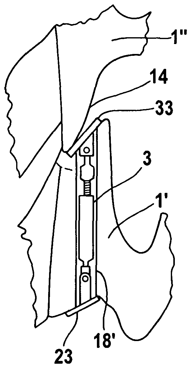
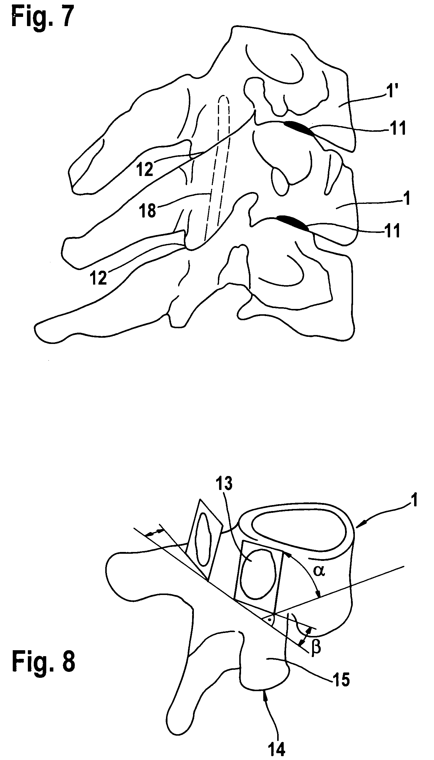
[0045]In FIG. 6, the prosthesis 3 according to the invention is shown in the implanted state. It will be seen that the bearing piece 33 rests on the upper articular surface 13, and the bearing piece 23 rests on the lower articular surface 14 of the vertebra 1′. The prosthesis 3 is therefore suitable for treating the facet joints 12 lying at two consecutive levels. The adjacent vertebrae can be fitted with one prosthesis 2 provided with a bearing piece 23, or once again with prostheses 3 extending over two levels, or, if appropriate, they may not be fitted with any prosthesis. By virtue of the bearing piece 23, 33 and its bearing shells 27, 37 being configured in accordance with the physiological circumstances, it is possible for the prosthesis 2, 3 to interact via its bearing shell 37 with the natural articular surface 13, 14 of the adjacent vertebra 1. As is shown in FIG. 3, the bearing shell 27 interacts with the prosthesis 2 in the vertebra 1.

[0046]For implantation of the second ...


PUM

PropertyMeasurementUnit
Forceaaaaaaaaaa
Pressureaaaaaaaaaa
Widthaaaaaaaaaa

Abstract

A prosthesis for facet joints of the spinal column includes a bearing piece and a guide rod. The bearing piece includes a pressure plate that is configured for resting on an articular surface of the vertebra and, on the opposite side, a bearing insert which has an articular surface configured for interacting with an articular surface of an adjacent vertebra. The guide rod is secured on the bearing piece by means of a pivot joint. The bearing forces are transmitted to the vertebra via the pressure plate. In this way, the guide rod can have a narrow configuration, such that a slit excavated in the vertebra for receiving the guide rod can also be made narrow to permit a simple and reliable implantation technique which at the same time is gentle on the bone substance.

Description

REFERENCE TO RELATED APPLICATION[0001]This application claims priority from U.S. Provisional Application No. 60 / 749,588, filed Dec. 13, 2005, the entire contents of which are incorporated herein by reference.FIELD OF THE INVENTION[0002]The invention relates to a prosthesis for facet joints of the spinal column, with a bearing piece and a retaining piece.BACKGROUND OF THE INVENTION[0003]Back problems can often be attributed to pathological changes in the area of the spinal column. One of the main causes lies in the interaction between two adjacent vertebrae and their connection. This in particular concerns intervertebral disks and facet joints. The connection between vertebrae may become damaged because of disease or overloading, either through injury or wear. This can lead to restricted movement, pain, or even loss of mobility. In the past, therapy was focussed on treating the intervertebral disks. Thus, various artificial joints were proposed which are implanted in place of a defec...

Claims


Application Information

Patent Timeline
IPC IPC(8): A61B17/70A61F2/44
CPCA61F2/4405A61F2002/30125A61F2002/30153A61F2002/30331A61F2002/30364A61F2002/30405A61F2002/30471A61F2002/30476A61F2002/3052A61F2002/30538A61F2002/3055A61F2002/30578A61F2002/30601A61F2002/30604A61F2002/30635A61F2002/30649A61F2002/30841A61F2002/30883A61F2002/30904A61F2002/449A61F2220/0025A61F2220/0033A61F2220/0091A61F2230/0008A61F2230/0019A61F2250/0006A61F2250/0007A61F2310/00029A61F2310/00796
Inventor LINK, HELMUT D.
Owner FACET LINK
Why Eureka
Try Eureka