
Optical lens device

A technology of optical devices and optical lenses, which is applied to lighting devices, components of lighting devices, light sources, etc., and can solve problems such as poor visual perception

Inactive Publication Date: 2011-09-21
EVERLIGHT ELECTRONICS
View PDF4 Cites 5 Cited by
  • Summary
  • Abstract
  • Description
  • Claims
  • Application Information

AI Technical Summary

Problems solved by technology

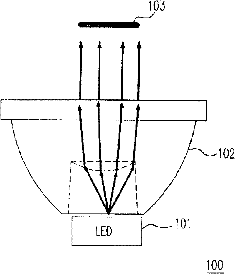
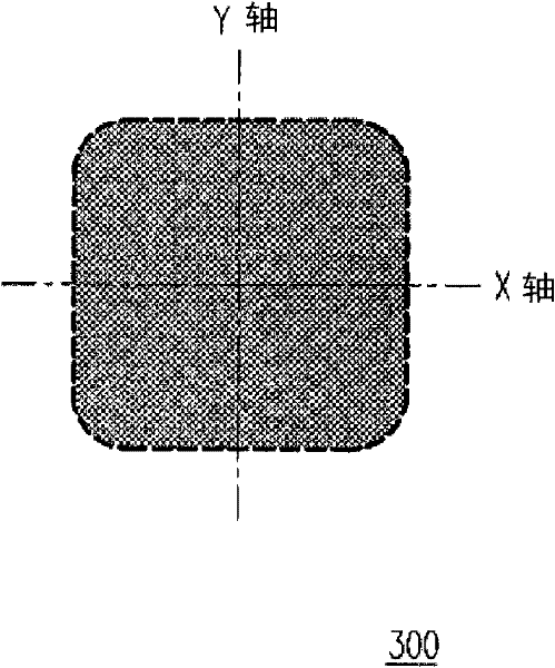
And the square luminous field type 300 will also give users a bad visual perception

Method used

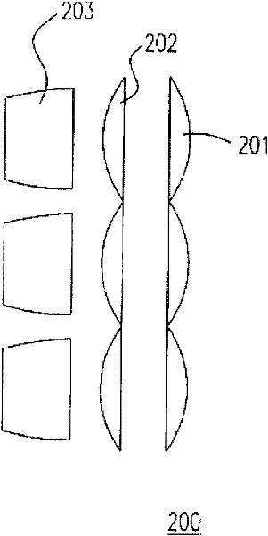

Image

  • Optical lens device
  • Optical lens device
  • Optical lens device

Examples


Embodiment Construction

[0029] See Figure 4 , Which is a schematic diagram of the first preferred embodiment of the present invention. The first preferred embodiment is a light emitting device 400 that includes a plurality of light emitting units 41, a plurality of reflective cups 42 and an optical lens device 43. The optical lens device includes a first lens 431, a second lens 432, and a third lens 433. The first lens 431 is a main lens, and the second lens 432 and the third lens 433 are secondary lenses. The first lens 431 has a first optical axis 4311, a first light-emitting optical axis 4312, and a first light-emitting field pattern 4313, wherein the first optical axis 4311 and the first light-emitting optical axis 4312 coincide. The second lens 432 has a second optical axis 4321, a second light-emitting optical axis 4322, and a second light-emitting field type 4323. The second lens 432 has a second optical axis 4321 and a second light-emitting optical axis 4322. The second included angle 4324 b...


PUM


Abstract

The invention provides an optical lens device. The optical lens device comprises a main lens and at least one secondary lens, wherein the main lens is provided with a first symmetric axis and a first optical axis, and the first symmetric axis is superposed with the first optical axis; and the at least one secondary lens is provided with a second symmetric axis and a second optical axis, the at least one secondary lens is arranged on four sides of the main lens, and the second symmetric axis is superposed with the second optical axis, wherein the main lens and the at least one secondary lens produce a uniform luminous field.

Description

Technical field [0001] The invention relates to an optical lens device, in particular to an optical lens device with a tilt lens. Background technique [0002] With the rising awareness of environmental protection such as energy saving and carbon reduction, the lighting tools in daily life are also developing towards high efficiency and low power consumption. For example, lighting fixtures using light-emitting diodes (LED), which have the advantages of small size, long life, low power consumption, fast response speed, and excellent shock resistance characteristics, have attracted more attention in recent years. However, because the light of the light-emitting diode has the characteristics of directivity and point light source, it is necessary to install an optical lens to reduce the directivity of lighting equipment used in other than condensing purposes to be suitable for lighting purposes. However, due to the structure of the existing optical lens, even if the directivity of t...

Claims


Application Information

Patent Timeline
Patent Type & Authority Applications(China)
IPC IPC(8): F21V5/04F21V13/04F21Y101/02F21Y115/10
Inventor 李建德裴建昌
Owner EVERLIGHT ELECTRONICS
Learn More