
Automated sequential planning of mr scans

一种规划、规划数据的技术,应用在磁共振测量、仪器、测量装置等方向,能够解决很难临床MRI图像再现性、临床图像不同质量水平、增加患者花费等问题,达到减少培训要求、消除操作者误差、避免变化性的效果

Active Publication Date: 2011-09-28
KONINK PHILIPS ELECTRONICS NV
View PDF4 Cites 29 Cited by
  • Summary
  • Abstract
  • Description
  • Claims
  • Application Information

AI Technical Summary

Problems solved by technology

The difficulty is that clinical images obtained by different operators will have different levels of quality
Furthermore, when setting the position and orientation of the stack of slices is performed manually, it is difficult to achieve reproducibility of clinical MRI images in e.g. subsequent procedures
When operators produce clinical images of poor quality, they will need to be redone
This is of course expensive for the hospital and adds to the cost of MRI examination of the patient

Method used


Image

  • Automated sequential planning of mr scans
  • Automated sequential planning of mr scans
  • Automated sequential planning of mr scans

Examples


Embodiment Construction

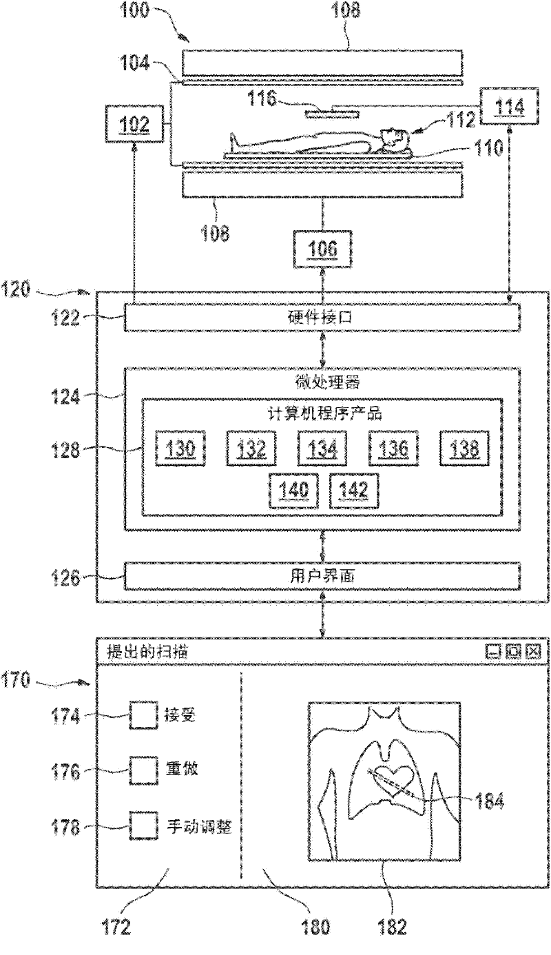
[0039] figure 1 An embodiment of an MRI scanner 100 capable of implementing embodiments of the invention is shown. There is a static magnet 108 that produces a large magnetic field, also referred to as BO, that is capable of aligning nuclear spins in a patient 112 or other subject with the BO field. A patient 112 is seated on a support 110 within the bore of the magnet. Gradient coils 104 are also located within the bore of the magnet and enable adjustment of the magnetic field. The transceiver coil 116 is adjacent to the volume of the patient 112 being imaged. This coil transmits and receives RF signals. In transmit mode, the coil generates an RF signal that produces a localized perturbation of the magnetic field for manipulating the orientation of the patient's 112 core spins. In receive mode, the phased array transceiver coils 116 receive RF signals caused by the rotation of the nuclear spins in the B0 field. The function of the transceiver coil can very generally be d...


PUM


Abstract

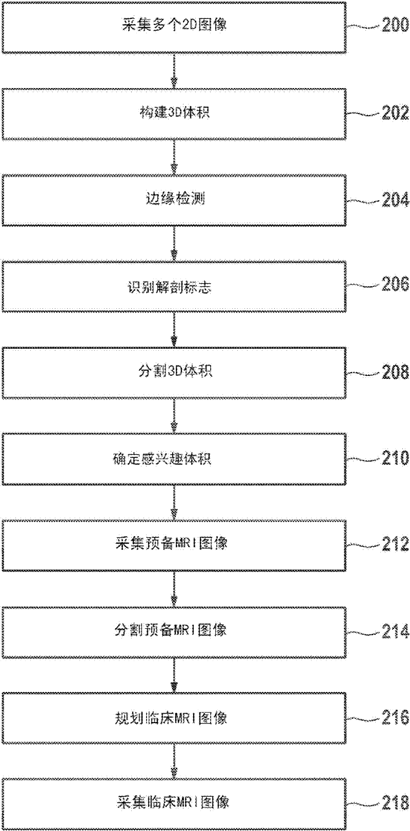
A method of acquiring at least one clinical MRI image of a subject comprising the following steps: acquiring a first survey image with a first field of view, the first survey image having a first spatial resolution, - locating a first region of interest and at least one anatomical landmarks in the first survey image, determining the position and the orientation of the first region of interest using the anatomical landmarks, the position and the orientation of the first region being used for - planning a second survey image, - acquiring the second survey image with a second field of view, the second survey image having a second spatial resolution, the second spatial resolution being higher than the first spatial resolution, generating a geometry planning for the anatomical region of interest using the second survey image, - acquiring a diagnostic image of the anatomical region of interest using the geometry planning.

Description

technical field [0001] The present invention relates to a method, device and computer program product for automatically acquiring clinical MRI image data. Background technique [0002] MRI scanners use huge static magnetic fields to align the nuclear spins of atoms as part of the process of producing images of the inside of a patient's body. This huge static magnetic field is called the B0 field. [0003] During an MRI scan, radio frequency (RF) pulses generated by a transmitter coil perturb the local magnetic field, and receiver coils detect RF signals emitted by nuclear spins. These RF signals are used to construct MRI images. These coils may also be referred to as antennas. Alternatively, the transmitter and receiver coils may be integrated into a single transceiver coil that performs both functions. It should be understood that use of the term transceiver coil also relates to systems using separate transmitter and receiver coils. This transmitted RF field is called ...

Claims


Application Information

Patent Timeline
Patent Type & Authority Applications(China)
IPC IPC(8): G01R33/54
CPCG01R33/543G01R33/5608G01R33/546G01R33/56383G01R33/54
Inventor C·J·F·M·伯格曼斯D·贝斯特罗夫H·S·黑泽M·考恩霍文J·M·登哈德A·W·西蒙内蒂W·德科克
Owner KONINK PHILIPS ELECTRONICS NV
Learn More