
Anti-dry protection device for electromagnetic oven cooker

A protection device, anti-dry-burning technology, applied to household appliances, household stoves/stoves, electric heating fuels, etc., can solve problems such as falling off, hidden dangers, affecting appearance, and achieve fast induction, accurate judgment and protection, and high precision. Effect

Active Publication Date: 2011-10-19
FOSHAN SHUNDE MIDEA ELECTRICAL HEATING APPLIANCES MFG CO LTD
View PDF5 Cites 3 Cited by
  • Summary
  • Abstract
  • Description
  • Claims
  • Application Information

AI Technical Summary

Problems solved by technology

[0002] At present, under the ceramic panel of the commercially available induction cooker, there are generally various ink screen printing patterns, and the temperature resistance of the ink is generally around 300 degrees. It affects the appearance, and there is a big safety hazard. If the protection is not timely, it may cause a fire due to the fire of the ink
[0003] Most of the existing anti-dry protection schemes are realized by the thermistor attached to the lower surface of the ceramic panel. Since the ceramic panel has a certain heat conduction process, it has a great influence on the accuracy of the thermistor's temperature measurement. As a result, the thermistor cannot accurately and quickly detect the temperature change at the bottom of the pot; at the same time, the thermistor itself has a certain signal delay, and cannot provide a control signal for the control system of the induction cooker in time; When dry-burning or other overheating conditions, the bottom of the pot will be in partial contact with the ceramic panel due to heat deformation, which will also cause the position of the thermistor to be out of contact with the overheated bottom of the pot and affect the accuracy of the thermistor detection

Method used

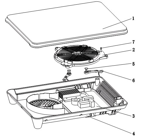

Image

  • Anti-dry protection device for electromagnetic oven cooker
  • Anti-dry protection device for electromagnetic oven cooker
  • Anti-dry protection device for electromagnetic oven cooker

Examples


Embodiment Construction

[0021] The specific implementation manners of the present invention will be further described below in conjunction with the drawings and examples.

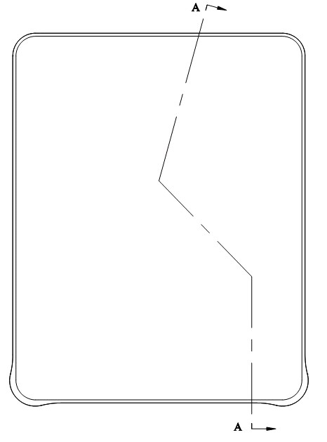
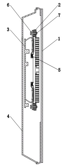
[0022] Such as figure 1 , figure 2 , image 3 As shown, the anti-dry burning protection device for electromagnetic cooker pots of the present invention includes a light-transmitting panel 1, a coil plate 2, a main control board 3, a base 4, and two photosensitive sensors that can induce changes in resistance due to dry-burning of pots and utensils. Component 5 and two photosensitive element brackets 6, wherein the coil disk 2 and the main control board 3 are installed in the base 4, and the two photosensitive element brackets 6 are installed under the coil disk 2, and one end thereof is fixed on the bracket of the coil disk 2 , the other end is located under the heating area of ​​the light-transmitting panel 1, and the photosensitive element 5 is clamped in the other end of the photosensitive element bracket 6, which is just lo...


PUM


Abstract

The invention relates to an anti-dry protection device for an electromagnetic oven cooker, comprising a light-transmitting panel (1), a coil disc (2), a main control plate (3) and a base (4), wherein the coil disc (2) and the main control plate (3) are arranged in the base (4). The anti-dry protection device is characterized by also comprising at least one photosensitive element (5) which is capable of inducting the dry and the reddening of the cooker to generate resistance change, is arranged in the base (4) by a photosensitive element support (6), is positioned below a heating zone of the light-previous panel (1) and is electrically connected with the main control plate (3). The anti-dry protection device creatively adopts the photosensitive element to judge the heating condition of theheated cooker on the electromagnetic oven cooker so as to prevent and control the dry burning of the cooker, therefore, the induction is fast, the precision is high, and the protection device has no signal delay, is not influenced by the installation environment, and can timely and accurately conduct the dry judgment and protection on the cooker.

Description

technical field [0001] The invention relates to an anti-dry-burning protection device for an electromagnetic cooker pot, which belongs to the improved technology for the safety protection of an electromagnetic cooker. Background technique [0002] At present, under the ceramic panel of the commercially available induction cooker, there are generally various ink screen printing patterns, and the temperature resistance of the ink is generally around 300 degrees. It affects the appearance, and there is a great potential safety hazard. If the protection is not timely, it may cause a fire due to the fire of the ink. [0003] Most of the existing anti-dry protection schemes are realized by the thermistor attached to the lower surface of the ceramic panel. Since the ceramic panel has a certain heat conduction process, it has a great influence on the accuracy of the thermistor's temperature measurement. As a result, the thermistor cannot accurately and quickly detect the temperatur...

Claims


Application Information

Patent Timeline
Patent Type & Authority Applications(China)
IPC IPC(8): F24C7/08
Inventor 刘杰张锦苏教能
Owner FOSHAN SHUNDE MIDEA ELECTRICAL HEATING APPLIANCES MFG CO LTD
Learn More