
Ship propelling unit and coupling dynamics test stand of ship body

A technology for coupling dynamics and propulsion devices, applied in the direction of mechanical bearing testing, etc., can solve problems such as large pulsation and impact, affecting the reliability and stability of ship propulsion device operation, and complex behavior of coupled dynamic systems

Inactive Publication Date: 2011-10-19
WUHAN UNIV OF TECH
View PDF4 Cites 24 Cited by
  • Summary
  • Abstract
  • Description
  • Claims
  • Application Information

AI Technical Summary

Problems solved by technology

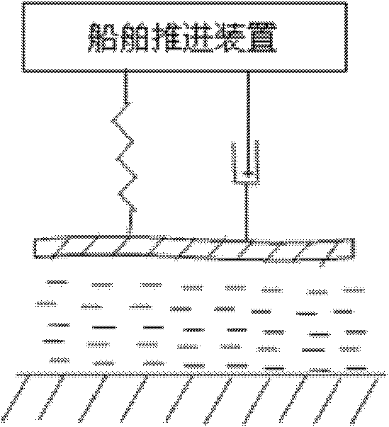
[0007] At the same time, large ship propulsion device-hull dynamics system (such as figure 1 (shown) has its own dynamics particularity. First, the propulsion power unit of the ship and the hull structure have strong coupling. It is a complex large-inertia and large-scale dynamic system composed of reciprocating motion and rotary motion. The pulsation of motion The general conventional rotor-bearing dynamics theory cannot solve the dynamic problems in the ship propulsion device; the second is the ship propulsion device-the hull system works on or under fluid water, and the hull structure Deformation, loading, and hull motion couple through the base to the shafting alignment and vibration of the ship's propulsion device, affecting the reliability and stability of the ship's propulsion device operation
Therefore, the behavior of the coupling dynamic system between the ship propulsion device and the hull is more complicated, and there are more coupling influencing factors, and there are scientific problems that need to be studied in depth

Method used


Image

  • Ship propelling unit and coupling dynamics test stand of ship body
  • Ship propelling unit and coupling dynamics test stand of ship body
  • Ship propelling unit and coupling dynamics test stand of ship body

Examples


Embodiment Construction

[0029] The shaft of the ship engine is installed on the support point of the bulkhead of the ship. When the cabin is subjected to external force, the bulkhead deforms, which makes the support point of the shaft produce relative displacement or relative displacement trend. figure 2 , 3 The coupling dynamics test bench device of the ship propulsion device and the hull shown simulates the above working conditions to verify the design rationality and reliability of the test piece shaft under the above working conditions and predict its life.

[0030] The specific implementation is as follows:

[0031] 1) The output shaft of the drive motor 1 enters the reducer 2 for deceleration, the output shaft of the reducer 2 drives the test piece shaft 7 to rotate through the elastic coupling 3, and a shaft end support frame 4 is fixedly supported at each end of the test piece shaft 7 , five floating bearings are placed in the shaft (take five floating bearings as an example), supported by ...


PUM


Abstract

The invention relates to a ship propelling unit and a coupling dynamics test stand of a ship body. The test stand mainly comprises a driving motor, a speed reducer, a test piece installation bracket, a vibration generator, a force sensor, a measurement and control system and a swing system, wherein the driving motor is decelerated by using the speed reducer; a tested piece shaft is driven to rotate by using an elastic coupling; the two ends of the tested piece shaft are provided with a fixed support point respectively; floating supports are arranged at a plurality of positions in the shaft; and a swing table is arranged below the test piece installation bracket. The test stand is developed and designed specific to a ship crankshaft, the floating supports are provided with excitation points, excitation in two directions can be generated by each excitation point, data such as applied load, bearing support force, shaft power, shaft system vibration and the like can be measured, and bases are provided for optimized designs of the structure and the installation way of the shaft by reducing the influence of a bulkhead under the action of external force during practical use of the crankshaft.

Description

Technical field: [0001] The invention relates to a coupling dynamics test bed for a ship propulsion device and a ship body. Background technique: [0002] The ocean contains abundant resources, and marine resources are the source of human survival. The development of marine resources has become a major strategic direction for the future development of all countries in the world. In order to better develop marine resources, the development of ship technology is an important technical basis and condition. In recent years, the United States, Germany, Japan, the United Kingdom, India and other major countries have entered into the development of marine resources in order to alleviate the shortage of domestic resources. platforms, competing for marine resources. [0003] In our country, in order to promote the development of ship economy and shipping industry and ensure the security of territory and marine resources in the southeast sea area of ​​our country, it is urgent to st...

Claims


Application Information

Patent Timeline
Patent Type & Authority Applications(China)
IPC IPC(8): G01M13/04
Inventor 袁成清严新平刘正林朱汉华郭智威宗成强李志雄
Owner WUHAN UNIV OF TECH
Learn More