Stand-by power supply automatic switch method for multi-stage series connection power supply network

A technology of self-switching and series power supply of backup power supply, applied in emergency power supply arrangement, electrical components, circuit devices, etc.

Active Publication Date: 2011-11-02
NARI NANJING CONTROL SYST
View PDF3 Cites 37 Cited by
  • Summary
  • Abstract
  • Description
  • Claims
  • Application Information

AI Technical Summary

Problems solved by technology

[0003] The technical problem to be solved by the present invention is to provide a new solution for standby automatic switching, which can solve the problem of relatively disordered operation of stan...

Method used


Image

  • Stand-by power supply automatic switch method for multi-stage series connection power supply network
  • Stand-by power supply automatic switch method for multi-stage series connection power supply network

Examples


Embodiment Construction

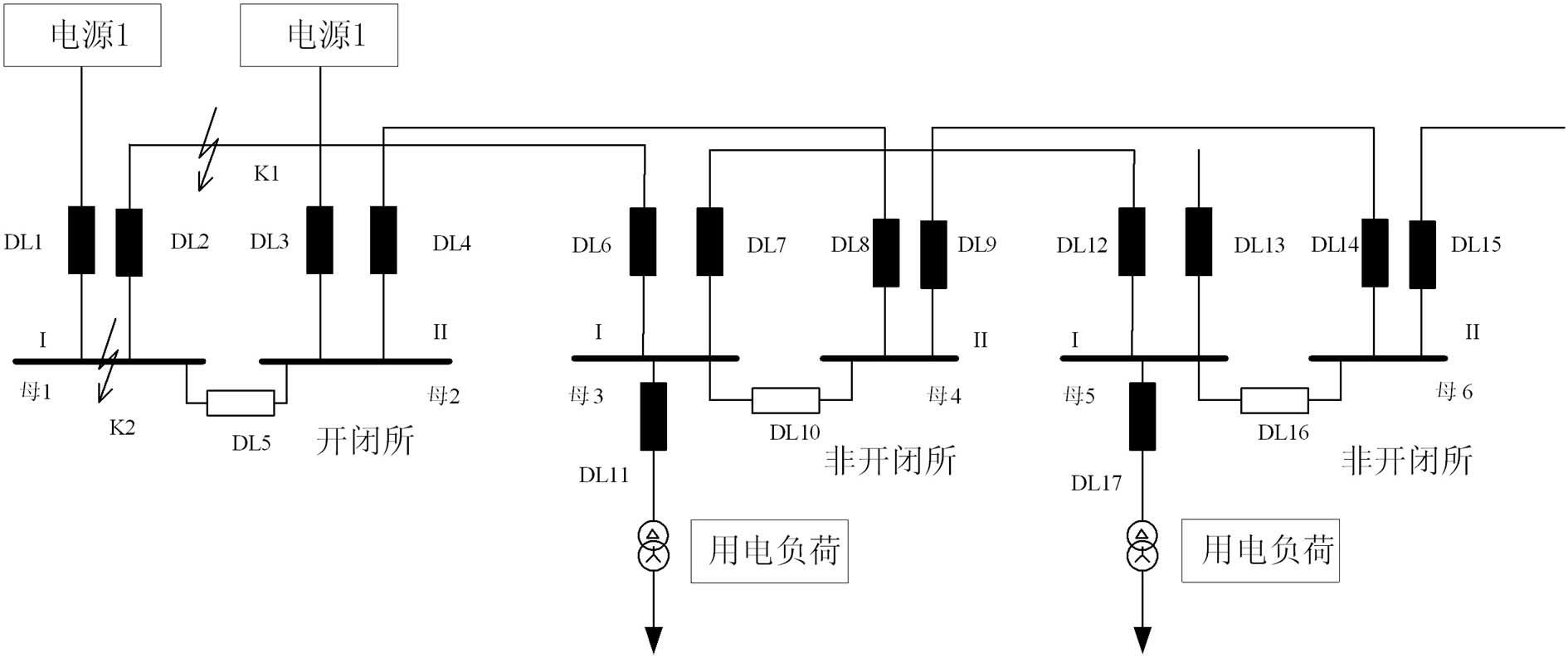
[0016] The following describes the implementation method of this new type of ring network power supply system in conjunction with the specific rail power supply network system. The main wiring structure of the rail power supply network ring network is as follows: figure 1 As shown, the normal power supply mode is two external power supply incoming lines each with several left and right busbars of substations, that is, split operation. The following analyzes the new type of standby automatic switching scheme according to several fault situations:

[0017] (1) Ring network line failure

[0018] When K1 fails, the optical fiber differential protection of the ring network line will trip, and the DL2 and DL6 switches will be tripped, resulting in the power loss of mother 3 and mother 5. At this time, the traditional backup switch will start the backup switch of DL10 and DL16 at the same time after a period of delay, changing the operation mode of all lower-level ring network non-o...


PUM


Abstract

The invention discloses a stand-by power supply automatic switch method for a multi-stage series connection power supply network, wherein the power supply network adopts ring network power supply, and a main power supply mode is that two external power source inlet wires carry left and right buses of a plurality of substations respectively. When a ring network line breaks down or a bus breaks down, a corresponding protective device eliminates fault and sends a switch connection signal through fiber transmission to a protective device of a next stage non switch substation simultaneously where the fault line locates, and sends a starting signal to a bus coupler stand-by power supply automatic switch device where next stage non switch locates. The stand-by power supply automatic switch device detects the starting signal, combined with a self voltage criterion, a remote signal state criterion and the like, determines whether to switch on the stand-by power supply or not simultaneously. Because a stand-by power supply automatic switch of a bus coupler switch of the next stage non switch substation where the fault line locates can not detect the starting signal, the stand-by power supply automatic switch performs no action. According to the invention, a problem that traditional stand-by power supply automatic switch function is lack of selectivity in ring network power supply systemapplication is solved.

Description

technical field [0001] The invention relates to a backup power supply self-switching method for a power system power supply network, in particular to a backup power supply self-switching realization method suitable for rail transit and other multi-stage series power supply networks, and belongs to the technical field of power supply systems. Background technique [0002] The rail transit power supply system has extremely high requirements for power supply security, so when the main power supply of the substation is lost due to a fault, it is necessary to require the backup power supply to be put into operation quickly and reliably. Since the rail transit power supply network generally adopts a multi-level series power supply network, the failure of the upper-level power supply may cause the simultaneous loss of power in the lower-level multi-level substations. According to the conventional configuration, the self-injection device of the backup power supply is generally solve...

Claims


Application Information

Patent Timeline
IPC IPC(8): H02J9/06H02H7/26H02H7/22
Inventor 吕良君王文进王汉林石秋生汤海宁朱颂怡
Owner NARI NANJING CONTROL SYST
Why Eureka
Try Eureka