Shading element, manufacturing method thereof and lens module

A manufacturing method and component technology, applied to optical components, optics, optical filters, etc., can solve problems such as large environmental impact and inability to meet the precision requirements of micro-optical components, and achieve low cost, prevent external electromagnetic interference, and simple manufacturing process Effect

Inactive Publication Date: 2014-12-31
HONG FU JIN PRECISION IND (SHENZHEN) CO LTD +1
View PDF2 Cites 0 Cited by
  • Summary
  • Abstract
  • Description
  • Claims
  • Application Information

AI Technical Summary

Problems solved by technology

However, with the development of miniaturization of lens modules, the current manufacturing processes are increasingly unable to meet the precision requirements of micro-optical components, and the yellow light, lithography, etching and other processes often used in the manufacturing process have a great impact on the environment

Method used


Image

  • Shading element, manufacturing method thereof and lens module
  • Shading element, manufacturing method thereof and lens module
  • Shading element, manufacturing method thereof and lens module

Examples


Embodiment Construction

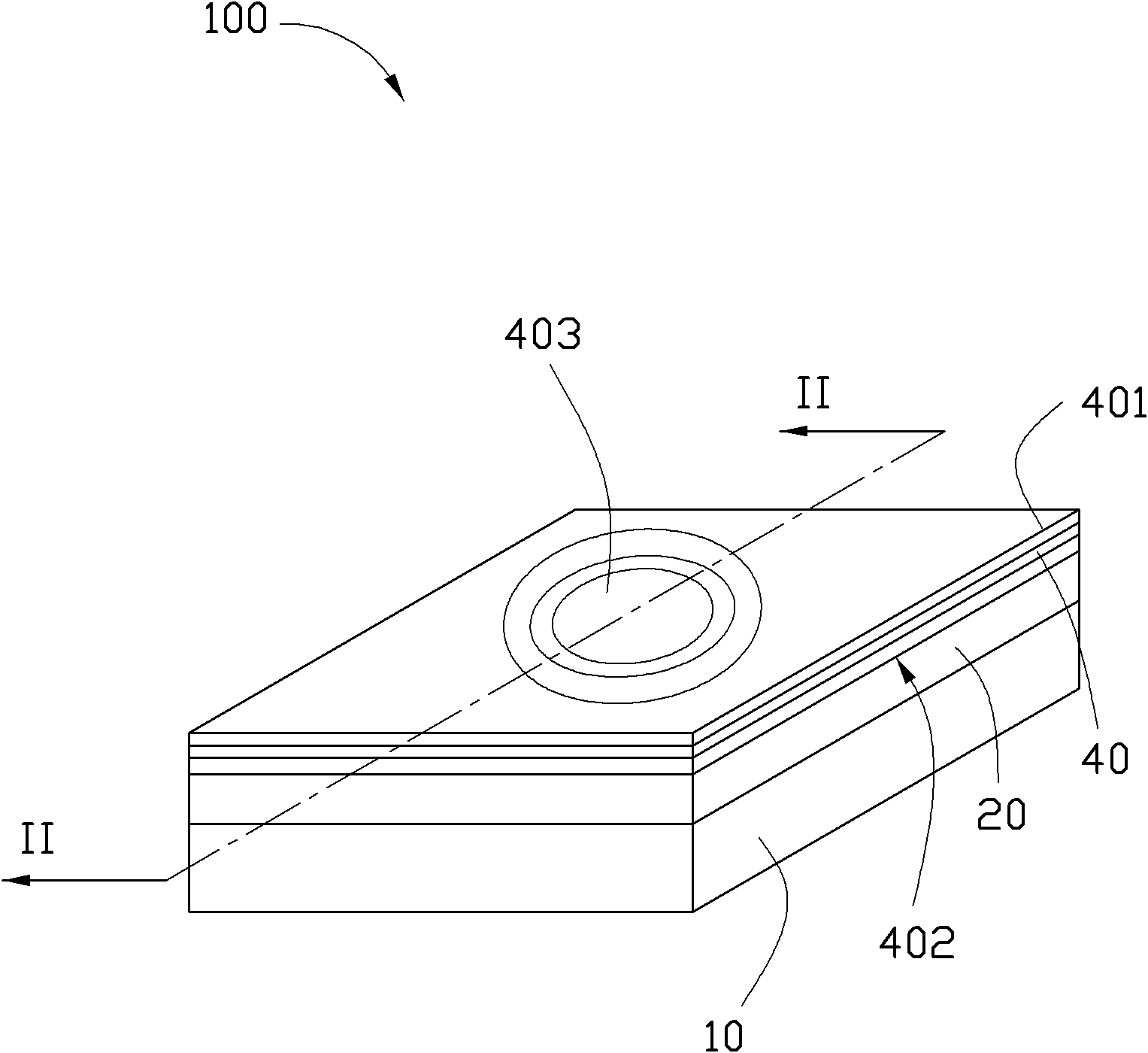
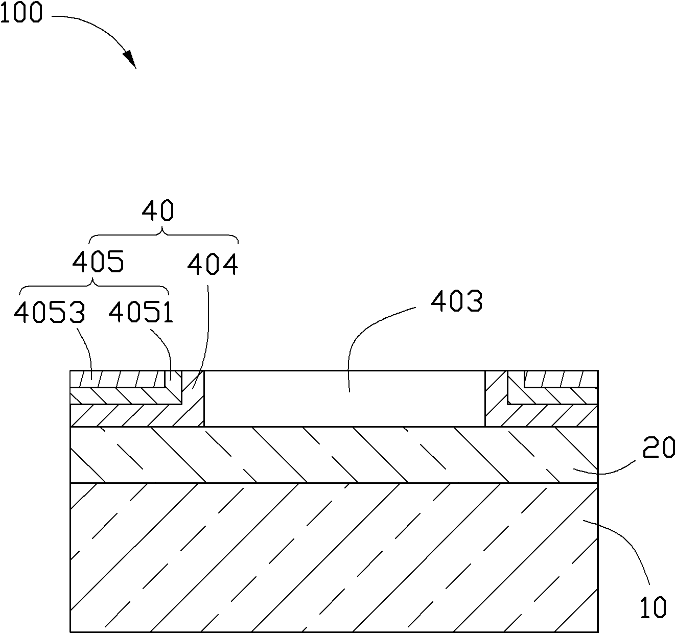
[0058] see figure 1 and figure 2 The light-shielding element 100 provided in the first embodiment of the present invention includes a light-transmitting flat plate 10 , a light-filtering layer 20 and a light-shielding shielding layer 40 arranged sequentially outward from the light-transmitting flat plate 10 .

[0059] The light shielding layer 40 has a top surface 401 away from the light-transmitting plate 10 , a bottom surface 402 close to the light-transmitting plate 10 , and a light-through hole 403 passing through the top surface 401 and the bottom surface 402 . The light shielding layer 40 includes a light shielding layer 404 formed on the filter layer 20 and a magnetic shielding layer 405 formed on the light shielding layer 404 . The part of the light shielding layer 40 away from the light through hole 403 is a magnetic shielding layer 405 and a light shielding layer 404 in sequence from the top surface 401 to the bottom surface 402 . The part of the light-shielding shi...


PUM


Abstract

The invention relates to a shading element. The shading element comprises a transparent flat plate and a shading shielding layer arranged on the transparent flat plate, wherein the shading shielding layer is provided with a top surface, a bottom surface and a light-transmitting hole penetrating the top surface and the bottom surface; the shading shielding layer comprises a magnetism-shielding layer and a shading layer which is sandwiched between the transparent flat plate and the magnetism-shielding layer; the magnetism-shielding layer and the shading layer are sequentially arranged on a part of the shading shielding layer away from the light-transmitting hole from the top surface to the bottom surface; and the shading layer and the magnetism-shielding layer are sequentially arranged on a part of the shading shielding layer close to the light-transmitting hole from the light-transmitting hole to the outer side. The invention also relates to a manufacturing method for the shading element and a lens module with the shading element.

Description

technical field [0001] The present invention relates to an optical element, in particular to a wafer-level shading element, a method for manufacturing the shading element, and a lens module array with the shading element. Background technique [0002] With the development of camera technology, the combination of lens modules and various portable electronic devices such as mobile phones, video cameras, computers, etc. has been favored by many consumers, so the market demand for miniaturized lens modules has increased. [0003] At present, miniaturized lens modules mostly use precision molds and other processes to manufacture micro-optical components, which are then electrically connected to image sensors made of silicon wafers, packaged, and then cut to obtain camera modules. However, with the development of miniaturization of lens modules, the current manufacturing process is increasingly unable to meet the precision requirements of micro-optical components, and the yellow l...

Claims


Application Information

Patent Timeline
Patent Type & Authority Patents(China)
IPC IPC(8): G02B5/00G02B5/20G12B17/04
Inventor 裴绍凯
Owner HONG FU JIN PRECISION IND (SHENZHEN) CO LTD
Why Eureka
Try Eureka