Vehicle-mounted optical lens
An optical lens and lens technology, applied in the field of optical lens, can solve problems affecting driver judgment, car accidents, vehicle form safety risks, etc., and achieve the effects of avoiding bending propagation, increasing reliability, and increasing convenience
- Summary
- Abstract
- Description
- Claims
- Application Information
AI Technical Summary
Problems solved by technology
Method used
Image
Examples
Embodiment 1
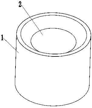
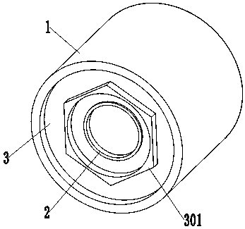
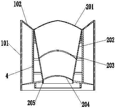
[0029] A vehicle-mounted optical lens, comprising a housing 1, a lens device 2, a connecting chassis 3, and a support frame 4, the connecting chassis 3 is screwed to the bottom of the housing 1, and the lens device 2 is arranged in the middle of the housing 1, The front end of the lens device 2 protrudes from the front end of the housing 1, the rear end of the lens device 2 is fixed on the connecting chassis 3, and the middle part of the connecting chassis 3 is provided with a light-transmitting hole 303, and the light-transmitting hole 303 is facing Lens device 2, a support frame 4 is provided on the outside of the lens device 2, the upper end of the support frame 4 is connected to the housing 1, the lower end of the support frame 4 is connected to the connecting chassis 3, and the inner wall of the support frame 4 Connect with lens unit 2.
Embodiment 2
[0031] A vehicle-mounted optical lens, comprising a housing 1, a lens device 2, a connecting chassis 3, and a support frame 4, the connecting chassis 3 is screwed to the bottom of the housing 1, and the lens device 2 is arranged in the middle of the housing 1, The front end of the lens device 2 protrudes from the front end of the housing 1, the rear end of the lens device 2 is fixed on the connecting chassis 3, and the middle part of the connecting chassis 3 is provided with a light-transmitting hole 303, and the light-transmitting hole 303 is facing Lens device 2, a support frame 4 is provided on the outside of the lens device 2, the upper end of the support frame 4 is connected to the housing 1, the lower end of the support frame 4 is connected to the connecting chassis 3, and the inner wall of the support frame 4 Connect with lens unit 2.
[0032] The housing 1 includes a light-shielding wall 101 and a front baffle 102, the light-shielding wall 101 is a cylindrical structur...
Embodiment 3
[0036] A vehicle-mounted optical lens, comprising a housing 1, a lens device 2, a connecting chassis 3, and a support frame 4, the connecting chassis 3 is screwed to the bottom of the housing 1, and the lens device 2 is arranged in the middle of the housing 1, The front end of the lens device 2 protrudes from the front end of the housing 1, the rear end of the lens device 2 is fixed on the connecting chassis 3, and the middle part of the connecting chassis 3 is provided with a light-transmitting hole 303, and the light-transmitting hole 303 is facing Lens device 2, a support frame 4 is provided on the outside of the lens device 2, the upper end of the support frame 4 is connected to the housing 1, the lower end of the support frame 4 is connected to the connecting chassis 3, and the inner wall of the support frame 4 Connect with lens unit 2.
[0037] The housing 1 includes a light-shielding wall 101 and a front baffle 102, the light-shielding wall 101 is a cylindrical structur...
PUM
 Abstract
Description
Claims
Application Information
 - R&D
- Intellectual Property
- Life Sciences
- Materials
- Tech Scout
- Unparalleled Data Quality
- Higher Quality Content
- 60% Fewer Hallucinations
Browse by: Latest US Patents, China's latest patents, Technical Efficacy Thesaurus, Application Domain, Technology Topic, Popular Technical Reports.
© 2025 PatSnap. All rights reserved.Legal|Privacy policy|Modern Slavery Act Transparency Statement|Sitemap|About US| Contact US: help@patsnap.com


