Temperature control rubber groove suitable for optic fiber gyroscope winding machine

A fiber optic gyroscope and loop winding machine technology, which is applied in the field of constant temperature control devices, can solve the problems of precise arrangement requirements of fiber jumpers, uneven winding of fiber loops, affecting quality and performance, etc., and achieves arbitrary adjustable position, constant temperature and high precision , cost reduction and application effect

Inactive Publication Date: 2013-01-16
BEIHANG UNIV
View PDF3 Cites 0 Cited by
  • Summary
  • Abstract
  • Description
  • Claims
  • Application Information

AI Technical Summary

Problems solved by technology

[0003] The fiber optic ring is the sensing core of the fiber optic gyroscope. In order to resist the influence of environmental vibration on the fiber optic ring, it is generally necessary to add a suitable filler during the winding process of the fiber. The viscosity of the glue also changes, which changes the amount of glue coated on the fiber, resulting in uneven winding of the fiber ring, affecting quality and performance
[0004] At present, there is no suitable constant temperature control device on some optical fiber ring machines, and the phenomenon of vacancy or fiber jumping in the winding optical fiber ring cannot meet the requirements of precise arrangement.

Method used


Image

  • Temperature control rubber groove suitable for optic fiber gyroscope winding machine
  • Temperature control rubber groove suitable for optic fiber gyroscope winding machine
  • Temperature control rubber groove suitable for optic fiber gyroscope winding machine

Examples


Embodiment Construction

[0035] The technical solutions in the present invention will be clearly and completely described below in conjunction with specific embodiments. Apparently, the described embodiments are only some of the embodiments of the present invention, not all of them. Based on the embodiments of the present invention, all other embodiments obtained by persons of ordinary skill in the art without making creative efforts belong to the protection scope of the present invention.

[0036] The embodiments of the present invention are further described in detail below.

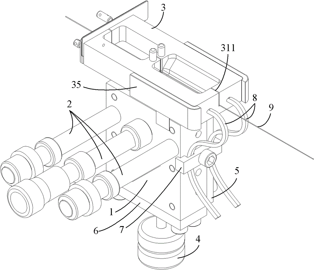
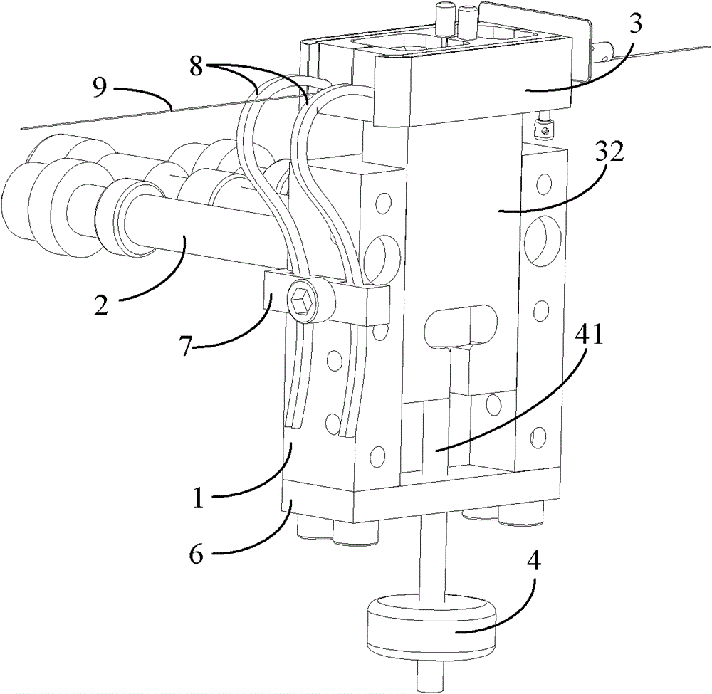
[0037] The embodiment of the present invention provides a temperature-controlled glue tank suitable for an optical fiber gyro winding machine, which can accurately control the constant temperature control of the coating process. Since the temperature value can be adjusted, it can adapt to the physical properties of various glues and other fillings Changes and changes in various winding process conditions. Such as figure 1 , ...


PUM


Abstract

The invention discloses a temperature control rubber groove suitable for an optic fiber gyroscope winding machine. In the temperature control rubber groove, a rubber groove seat has a square groove body structure; the back wall of a groove body is provided with a positioning shaft; a heating rubber groove assembly is arranged in the rubber groove seat groove body; the upper end of the heating rubber groove extends out above the rubber groove seat; the heating rubber groove is provided with an aperture for an optical fiber to pass; the lower end of the heating rubber groove is connected to an adjusting nut; the adjusting nut extends out of the lower end of the rubber groove seat; the front wall of the rubber groove seat is provided with a rubber groove pressing block for pressing the heating rubber groove assembly in the rubber groove seat groove body; a heater and a temperature sensor are arranged in the heating rubber groove assembly; and the bottom of the rubber groove seat is provided with a rubber groove seat baffle plate for fixedly blocking a notch with a bolt. The temperature control rubber groove has an adjustable temperature value, high constant-temperature accuracy, highprocess adaptability, a small size and an optionally adjustable position, is convenient for improving the winding process of the optic fiber gyroscope winding machine, and is convenient to match withother mechanisms; and a general temperature control method in which a heater is matched with a temperature sensor is adopted, so that the cost can be lowered conveniently.

Description

technical field [0001] The invention relates to a temperature-controlled glue tank suitable for an optical fiber gyroscope winding machine, more particularly, a device that realizes constant temperature control during the process of coating glue on precision-wound optical fibers on an optical fiber winding machine. Background technique [0002] The fiber optic gyroscope was born in 1976. It is a new type of sensor that uses fiber optic sensing technology to measure the space inertial rotation rate. It has developed into a new mainstream instrument with epoch-making characteristics in the field of inertial technology. Compared with the laser gyroscope developed here, it has higher precision, low cost, small size and light weight. The application prospect of fiber optic gyroscope is very broad. It is not only used in the navigation of aircraft and ships, missile guidance, high-precision position control of spacecraft, but also in the guidance of high-end cars in civilian use, ...

Claims


Application Information

Patent Timeline
Patent Type & Authority Patents(China)
IPC IPC(8): C03C25/16
Inventor 董全林张春熹王夏霄潘雄迟悦李慧鹏杨德伟徐宏杰宋凝芳李立京贾明章博刘海霞孟昭魁邵洪峰孟凡念袁水平于成交杨彦杰孙茂多
Owner BEIHANG UNIV
Why Eureka
Try Eureka