Temperature-compensation circuit for primary side feedback system and method of isolated power converter

A technology of temperature compensation circuit and power converter, which is applied in the direction of output power conversion devices and electrical components, and can solve the problem of different output voltages of isolated power converters

Inactive Publication Date: 2011-11-23
RICHPOWER MICROELECTRONICS
View PDF5 Cites 3 Cited by
  • Summary
  • Abstract
  • Description
  • Claims
  • Application Information

AI Technical Summary

Problems solved by technology

[0007] The purpose of the present invention is to propose a temperature compensation circuit and method for a primary side feedback system to solve the problem of different output voltages of isolated power converters due to ambient temperature

Method used


Image

  • Temperature-compensation circuit for primary side feedback system and method of isolated power converter
  • Temperature-compensation circuit for primary side feedback system and method of isolated power converter
  • Temperature-compensation circuit for primary side feedback system and method of isolated power converter

Examples


Embodiment Construction

[0014] The specific implementation manners of the present invention will be described in detail below in conjunction with the accompanying drawings.

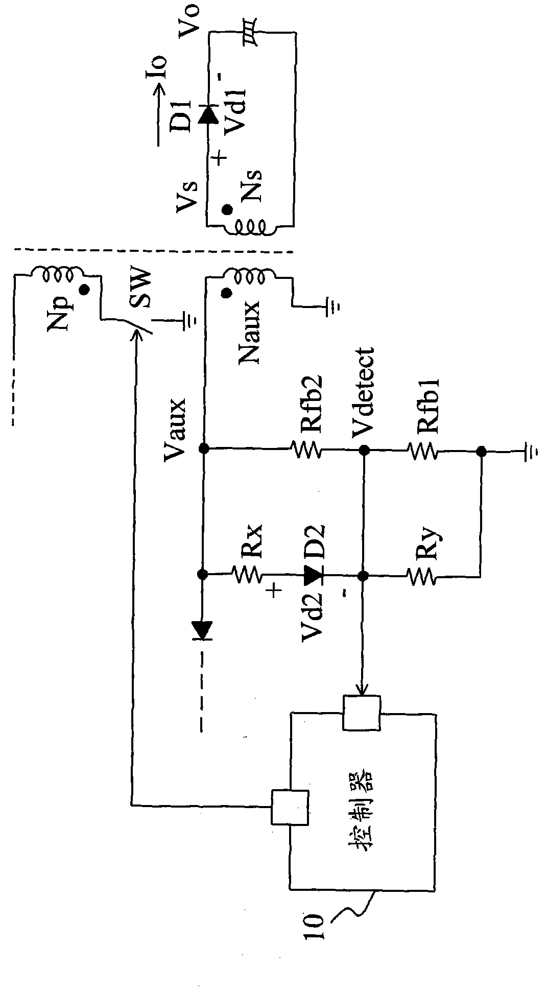
[0015] figure 2 is an embodiment of the present invention. The feedback circuit uses a resistor divider to divide the induction voltage Vaux of the auxiliary coil Naux to generate a feedback voltage Vdetect at the feedback terminal Vdetect. The resistor divider includes a resistor Rfb2 connected between the auxiliary coil Naux and the feedback terminal Vdetect , and the resistor Rfb1 is connected between the feedback terminal Vdetect and the ground terminal. The compensation diode D2 is connected between the auxiliary coil Naux and the feedback terminal Vdetect. Preferably, it has the same temperature characteristics as the output diode D1. For example, the forward bias voltages Vd1 and Vd2 of the two diodes D1 and D2 have negative temperature coefficients. , For example, Vd1 and Vd2 each decrease by 2mV for every 1°C increas...


PUM


Abstract

The invention discloses a temperature-compensation circuit for a primary side feedback system and method of an isolated power converter. A forward bias voltage changing following the temperature change of a compensation diode which has a temperature characteristic as same as the temperature characteristic of an output diode is utilized to control an induced voltage of an auxiliary coil, so as to cancel out the change of an output voltage caused by the forward bias voltage changing following the temperature change of the output diode.

Description

technical field [0001] The invention relates to a power converter, in particular to a temperature compensation circuit and method for a primary side feedback system of the power converter. Background technique [0002] Isolated power converters require a feedback system to reflect output information to the controller. The secondary side feedback system uses a voltage regulator (shunt regulator TL431), an optocoupler, and peripheral resistors and capacitors, which require high costs. The primary side feedback system directly detects the voltage signal of the auxiliary coil as the feedback signal of the secondary side output, so the cost can be reduced, but the temperature effect of the secondary side may cause an error in the output voltage. like figure 1 As shown, the number of turns of the secondary side coil and the induced voltage are Ns and Vs respectively, so the induced voltage of the auxiliary coil Naux [0003] Vaux = Vs ...

Claims


Application Information

Patent Timeline
Patent Type & Authority Applications(China)
IPC IPC(8): H02M1/32
Inventor 陈昇华林梓诚黄培伦
Owner RICHPOWER MICROELECTRONICS
Why Eureka
Try Eureka