Inertia-free fishing reel preventing twisting of fishing-line

A fishing line and inertial technology, applied in fishing reels, fishing, applications, etc., can solve the problems of increased wear of fishing lines, inability to completely eliminate winding, tension, etc.

Inactive Publication Date: 2013-10-16
亚历桑大·拉费罗维奇·尼亚泽夫
View PDF7 Cites 0 Cited by
  • Summary
  • Abstract
  • Description
  • Claims
  • Application Information

AI Technical Summary

Problems solved by technology

[0006] Non-inertia fishing reels have a common defect: the fishing line is twisted along its own axis each time it is thrown, and after many cycles of throwing, the fishing line is entangled and tightened under the action of elasticity
[0008] The well-known disadvantage of the coil is that the winding cannot be completely eliminated
Forced line throwing increases fishing line wear

Method used


Image

  • Inertia-free fishing reel preventing twisting of fishing-line
  • Inertia-free fishing reel preventing twisting of fishing-line
  • Inertia-free fishing reel preventing twisting of fishing-line

Examples


Embodiment Construction

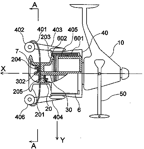
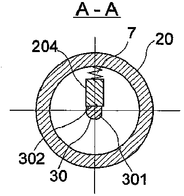
[0020] The schematic diagram of the structure of the inertialess fishing reel to avoid fishing line entanglement is shown in figure 2 with image 3 .

[0021] The line pipe 20 has two working side plates 201 and 203, the line pipe 20 is connected to the shaft 30, can be inserted into the shaft from any direction, and can be easily removed from the shaft. In order to prevent the wire tube 20 from rotating on the shaft 30, the wire tube 20 has a truncated circle 301, and the wire hole of the wire tube 20 is similarly shaped. In order to keep the wire tube 20 from moving along the shaft 30 , the wire tube 20 is fixed by two elastic detents 204 and 205 , while the shaft 30 is fixed by a groove 302 . Due to the bayonet pins, when the wire pipe is sleeved on the shaft, any one of the bayonet pins partially penetrates into the groove 302 under the action of the spring 7, thereby blocking the wire pipe. To remove the conduit 20, the detent 204 can be pulled out of the groove 302 w...


PUM


Abstract

The invention relates to the field of sport fishing and amateur fishing and can be used in the design and manufacture of inertia-free fishing reels. According to the invention, the reel spool has two working skirts. The spool is fastened to a spindle in a manner such that the spool is slipped onto the spindle and is fastened thereon from two sides. A line roller has two rollers for rolling the line onto the spool in either of two possible directions of rotation. The working skirt not being used is covered by a cylindrical cover to keep the line free behind the spool. During use of the reel, the spool is reversed on the spindle as necessary and the working direction of rotation of the line roller is changed. For convenience of use of the reel, the hauling mechanism can be reversible.

Description

technical field [0001] The present invention relates to the field of sports and leisure fishing, namely about the structure of the inertialess fishing reel. Background technique [0002] figure 1 The structure of a common inertialess fishing reel is listed in , including a housing 1, a fishing line spool 2, a fishing spool 3, a fishing line layer 4 with a clip 41 installed, a pulley 42, rotating rods 43 and 44, and a manual Device handle 5. A traction mechanism (not shown), a mechanical device (not shown) for increasing the reciprocating motion of the shaft, and a friction device (not shown) are installed on the casing 1 . [0003] Before throwing, open the clips 41 on the rotating rods 43 and 44, that is, turn over along the Y axis perpendicular to the X axis, turn over to the position where the clips will not hinder the fishing line from the line tube. When cast, the fishing line is shed from the stationary spool 2 by its smooth working side plate 21 . In order to wind...

Claims


Application Information

Patent Timeline
Patent Type & Authority Patents(China)
IPC IPC(8): A01K89/00
CPCA01K89/0111A01K89/0108A01K89/01083A01K89/011221
Inventor 亚历桑大·拉费罗维奇·尼亚泽夫
Owner 亚历桑大·拉费罗维奇·尼亚泽夫
Why Eureka
Try Eureka